Current diverter strip and methods

a diverter strip and current technology, applied in the direction of corona discharge, instruments, aircraft static dischargers, etc., can solve the problems of affecting extensive damage to the underlying antenna and sensitive electronics, so as to reduce the radio frequency performance of the underlying antenna, inhibit the puncture of the radome, and facilitate the application of the radom

Active Publication Date: 2005-02-24
HALL ALLEN L
View PDF8 Cites 44 Cited by
  • Summary
  • Abstract
  • Description
  • Claims
  • Application Information

AI Technical Summary

Benefits of technology

[0007] According to an example of the invention, a current diverter strip is configured to initiate an ionized channel in the presence of an electric field, to redirect lightning current away from sensitive equipment. The invention may have a minimal impact on the radio frequency performance of any underlying antennas, may be capable of diverting multiple lightning strikes, may be weather and chemical resistant, may be visually appealing, including colorable, and/or may be readily applied to radomes, aerospace vehicles or other structures.
[0008] According to an implementation of the invention, a thin dielectric has closely spaced conductive segments aligned longitudinally on the underside of the dielectric. The underside of the dielect

Problems solved by technology

Such lightning strikes cause considerable degradation of the radome structure and extensive damage to the underlying antenna and sensitive electronics.
The lightning diverter strip may have a detrimental impact on the underlying antenna's radio frequency performance.
The lightning diverter strip may be damaged during a lightning strike, t

Method used


Image

  • Current diverter strip and methods
  • Current diverter strip and methods
  • Current diverter strip and methods

Examples


Embodiment Construction

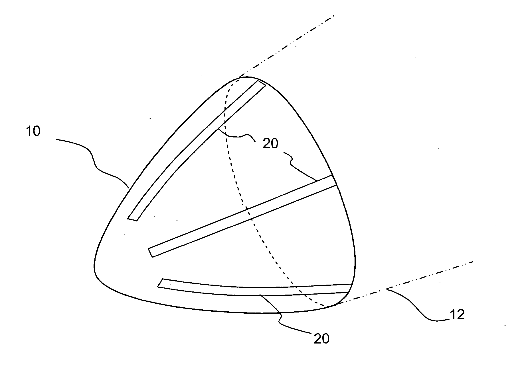
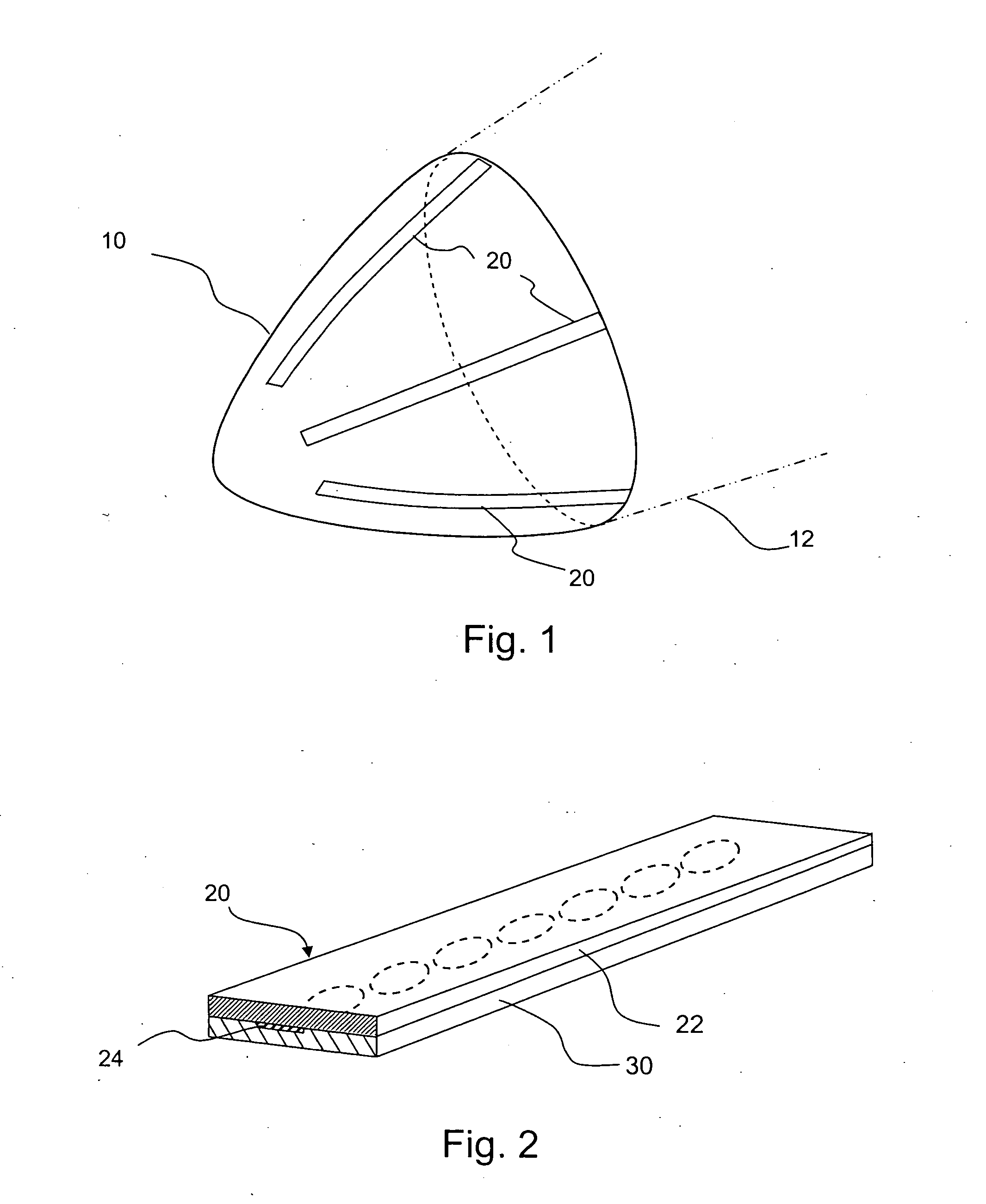
[0026] The present invention can be used to divert current by providing an ionized path to guide the current, and can be used in a wide variety of applications. Examples include use on an aircraft, a wind turbine, electrical transmission equipment and other applications involving potential exposure to undesirable current. When exposed to electric fields, such as electric fields associated with lightning, the current diverter strip of the invention can form an ionized channel in an area near the diverter strip that conducts the undesirable current from the item protected by the current diverter strip. Undesirable current can be current of an undesirably high amperage. Often, undesirable current also results in associated undesirable, excessive voltages. Other embodiments can be used to shunt undesirable voltages and currents, such as those that may be present on electrical conductors, from sensitive electrical or electronic equipment.

[0027] One example implementation of the inventio...


PUM


Abstract

A current diverter strip is provided having a dielectric (22) located above a plurality of conductive segments (24). An insulator (30) is also provided among said conductive segments (24) and below said dielectric (22). When RF transparency is required, the conductive segments (24) can have a maximum dimension that is approximately 1/6th of a wavelength of the highest operating frequency of an antenna that may be communicating through the current diverter strip. The dielectric (22) may be colored to match the color of the structure to which it is implemented. Upon exposure to a strong electric field, the current diverter strip (20) forms an ionized channel above the dielectric (22). In various implementations, the current diverter strip may be radio frequency transparent, environmentally and chemically resistant, color matched to its surroundings, and/or can withstand repeated uses.

Description

CROSS-REFERENCE TO RELATED APPLICATIONS [0001] This Patent Application claims priority to U.S. Provisional Patent Application No. 60 / 496,347, filed on Aug. 18, 2003, the contents of which are incorporated herein by reference in its entirety.FIELD OF THE INVENTION [0002] This invention relates generally to the diversion of current and more specifically to the creation of an ionized path to divert current. BACKGROUND [0003] Arcing current, such as a lightning strike, can attach to conductive objects near or contained within non-conductive enclosures. For example, lightning has penetrated nose radomes on aircraft and forced lightning currents in excess of 200,000 amperes into the antennas and other sensitive electronics underneath the nose radomes. Such lightning strikes cause considerable degradation of the radome structure and extensive damage to the underlying antenna and sensitive electronics. [0004] Lightning diverter strips have been devised in the past to prevent lightning punct...

Claims


Application Information

Patent Timeline
IPC IPC(8): B64D45/02
CPCB64D45/02
Inventor HALL, ALLEN L.
Owner HALL ALLEN L
Why Eureka
Try Eureka