Clutch suitable for vehicles' powered mirrors

Active Publication Date: 2014-04-03
FICO MIRRORS SA
View PDF6 Cites 5 Cited by
  • Summary
  • Abstract
  • Description
  • Claims
  • Application Information

AI Technical Summary

Benefits of technology

[0031]Welding process expands the end of the shaft avoiding the second body to be released. The second body has a cavity located, according to the longitudinal axis, at the location of the expandable region of the end of the shaft. When the end of the shaft is expanded, the expanded region is housed in the cavity and provide

Problems solved by technology

When the mirror reaches the end of stroke the torque of the motor is

Method used


Image

  • Clutch suitable for vehicles' powered mirrors
  • Clutch suitable for vehicles' powered mirrors
  • Clutch suitable for vehicles' powered mirrors

Examples


Embodiment Construction

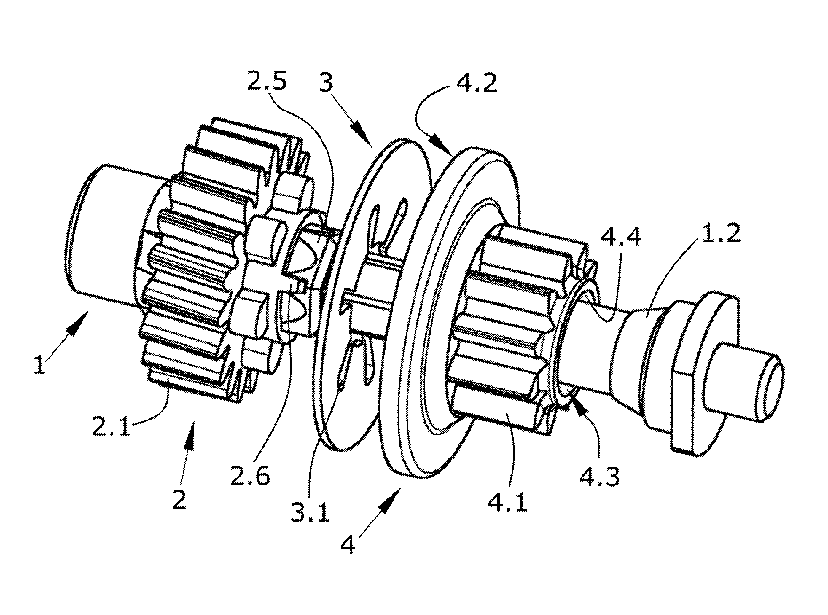
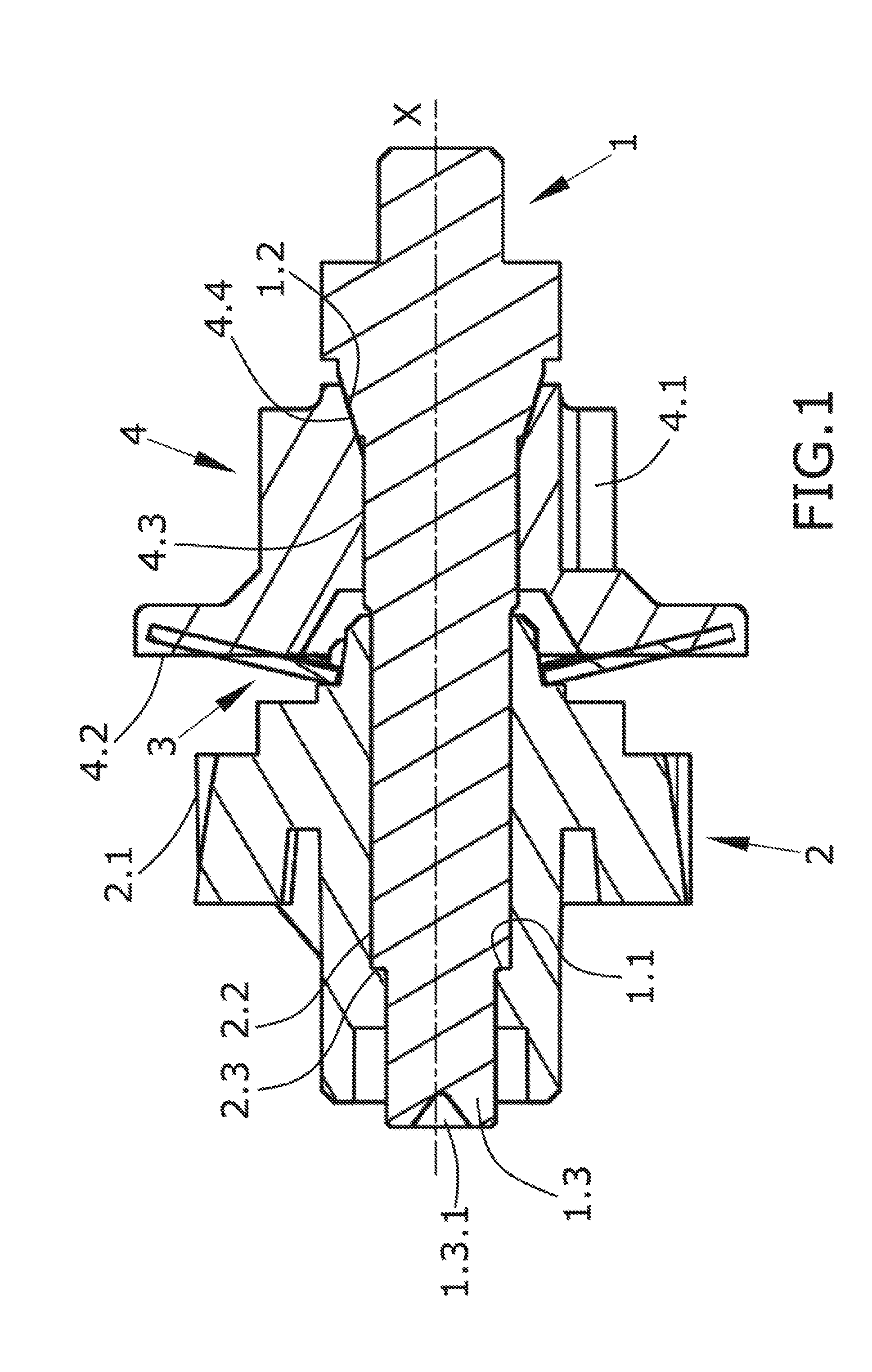
[0039]The present invention, according to its first inventive aspect, is a clutch suitable for powered mirrors whose central element is a shaft (1); this shaft (1) is the reference element that establishes the relative position of other elements of the clutch, such as the first body (4) and the second body (2). Its longitudinal axis, named as axis (X), is also the reference used to define the particular configurations and orientation of the clutch parts.

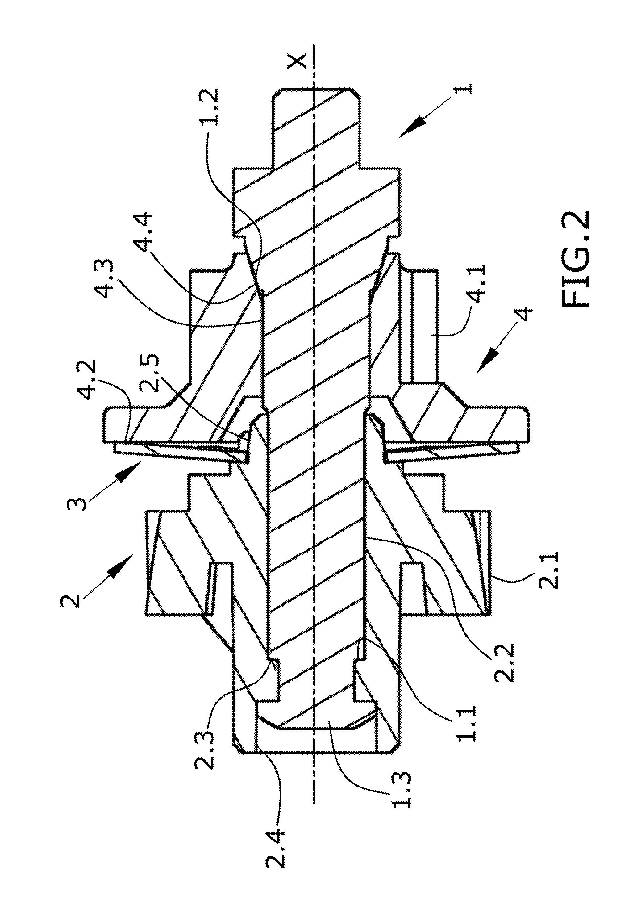
[0040]As can be seen in the embodiment shown in FIG. 1, one of the distal ends of the shaft (1), concretely the one located on the left-hand side of this figure, is an end (1.3) of the shaft (1) adapted to be expanded. In the example of FIG. 1, this end has an inner conical cavity (1.3.1) which can be used for said expansion, for example by means of the introduction of an ultrasound device which induces a welding process or of a welding tip. FIG. 2, on the contrary, shows this end (1.3) of the shaft (1) once the expansion has taken p...


PUM


Abstract

The present invention relates to a clutch mechanism preferably used in a vehicle door mirror with a high durability and which allows reaching, in a fast and simple way, a preset compression level owing to the existence of two limiting surfaces

Description

CROSS-REFERENCE TO RELATED APPLICATION[0001]This application claims priority to European Patent Application No. 12382383.3 filed on Oct. 2, 2012 under the provisions of 35 U.S.C. 119. The entire contents of the foregoing European patent application are hereby incorporated by reference herein, for all purposes.OBJECT OF THE INVENTION[0002]The present invention relates to a clutch suitable for powered mirrors preferably for vehicles. Powered mirrors have electrical motors that orientate the mirror according to the signals commanded by the user. When the mirror reaches the end of stroke the torque of the motor is increased and the gears of other parts of the device can be damaged. Clutches are used to limit the maximum torque applied to the kinematic chain of the device transferring the movement from the motor to the mirror.[0003]When the torque reaches a maximum value, some internal pieces of the clutch slip and the energy is dissipated because the friction of said pieces.[0004]The pr...

Claims


Application Information

Patent Timeline
IPC IPC(8): F16D13/38
CPCF16D13/38B60R1/072F16D1/072F16D7/024F16D7/028F16D43/213F16D43/218
Inventor CABALLERO TAPIA, MOISES
Owner FICO MIRRORS SA
Why Eureka
Try Eureka