
Handrail Assembly

a technology of handrails and mounting brackets, which is applied in the field of supporting devices, can solve the problems of increasing the cost of storage, packaging and transportation of safety handrails, difficulty in assembly of safety handrails by users, and difficulty in mounting safety handrails on the wall, so as to facilitate and reduce storage, packaging and transportation costs, and enhance the resilience and fixedness of each connecting tube. the effect of easy and convenient assembly

Inactive Publication Date: 2014-04-10
SHINE IND
View PDF8 Cites 12 Cited by
  • Summary
  • Abstract
  • Description
  • Claims
  • Application Information

AI Technical Summary

Benefits of technology

This patent describes a handrail assembly that is easy to assemble and cost-effective to store, pack, and transport. The assembly includes multiple connecting units and extension units that are connected step by step, making assembly simple. The connecting units and extension units are detached before assembly to save on storage, packaging, and transportation costs. The connecting tubes of the connecting units are designed to fit tightly onto the mounting pipe of each extension unit, and reinforcing ribs are added for enhanced resiliency and fixedness. Overall, this handrail assembly provides convenient assembly, cost savings, and improved design for durability.

Problems solved by technology

However, when the handrail is mounted on a longer passageway, it is necessary to provide multiple handrails which are connected together to form a longer safety handrail so that the safety handrail cannot be mounted on the wall easily and conveniently, thereby causing difficulty to the user in assembly of the safety handrail.
In addition, the safety handrail cannot be detached before assembly so that the safety handrail has a larger volume, thereby causing inconvenience in and increasing the cost of storage, packaging and transportation of the safety handrail.

Method used


Image

  • Handrail Assembly
  • Handrail Assembly
  • Handrail Assembly

Examples


Embodiment Construction

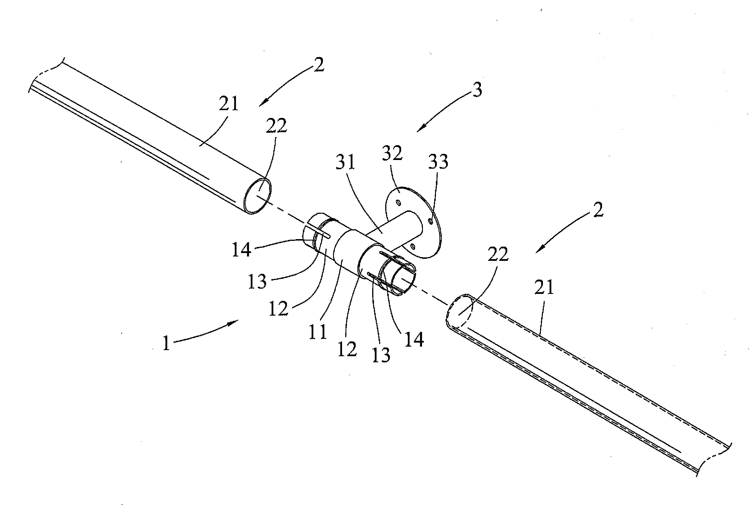
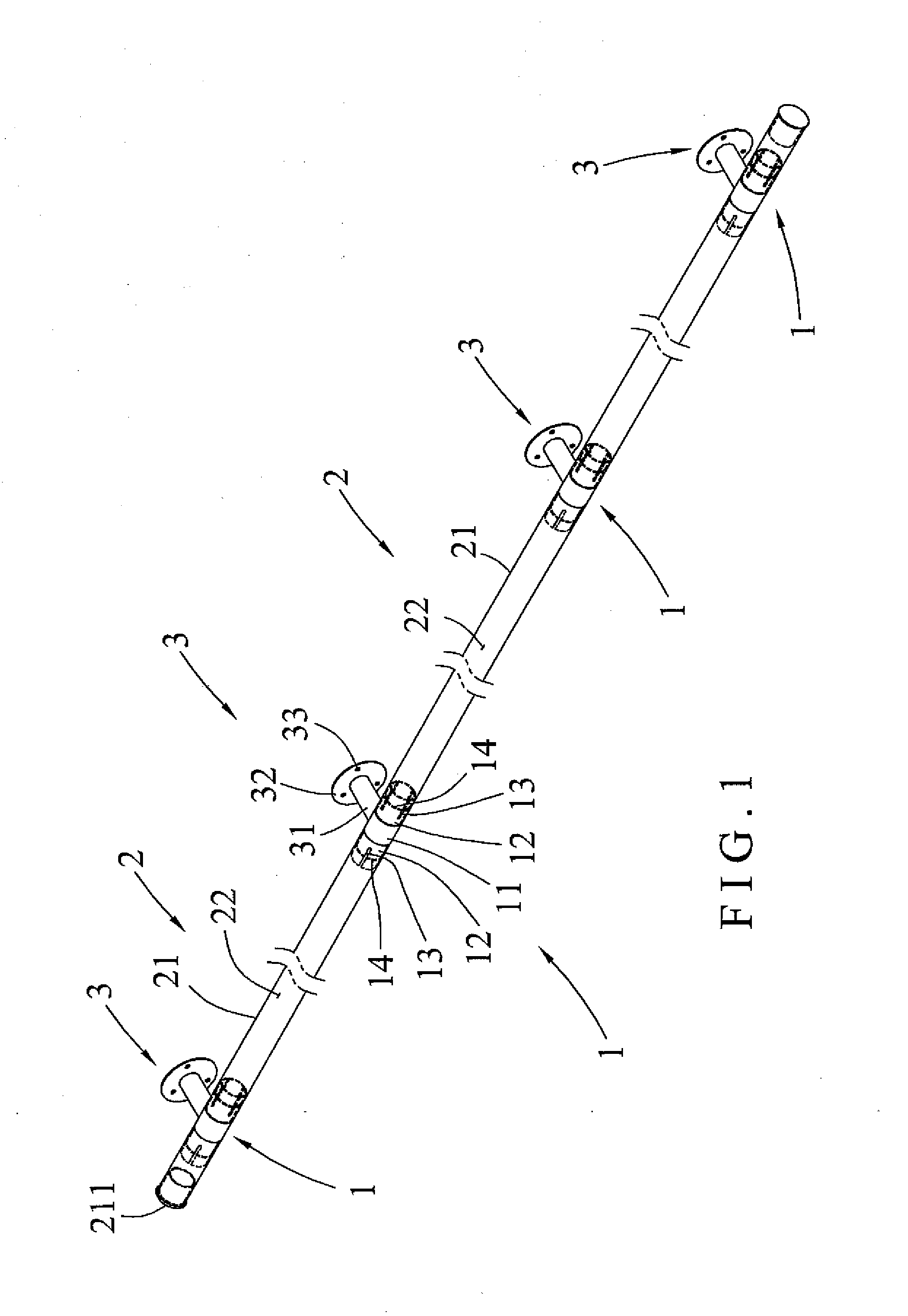
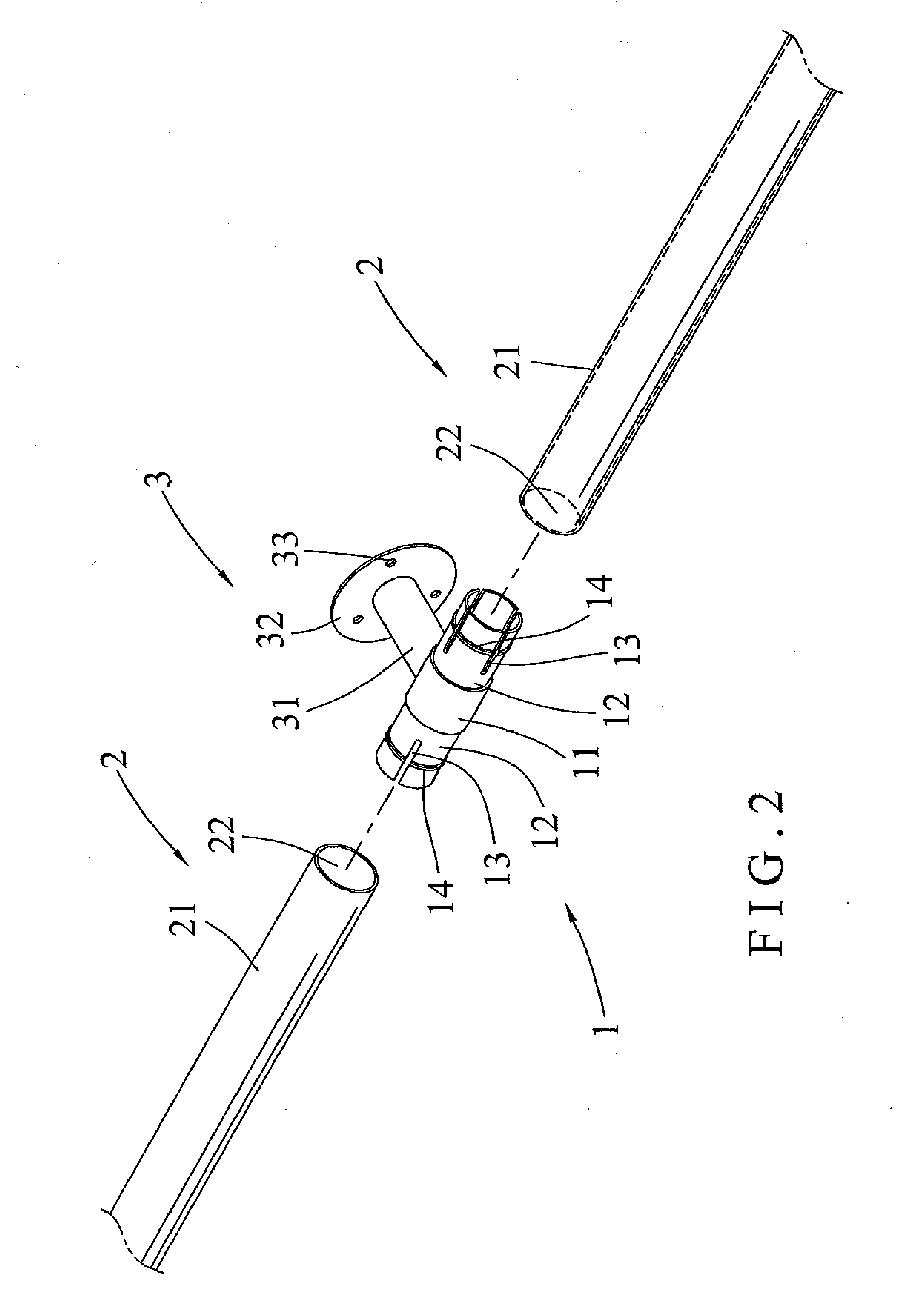
[0020]Referring to the drawings and initially to FIGS. 1-4, a handrail assembly in accordance with the present invention comprises at least one connecting unit 1, and at least two extension units 2 each connected with the connecting unit 1. In the preferred embodiment of the present invention, the handrail assembly comprises a plurality of connecting units 1, a plurality of extension units 2 connected with the connecting units 1 respectively, and a plurality of support units 3 connected with the connecting units 1 respectively.

[0021]The connecting unit 1 is made of a metallic material and includes a middle tube 11 and two connecting tubes 12 extended from two opposite ends of the middle tube 11 respectively. Each of the connecting tubes 12 of the connecting unit 1 has a surface formed with a plurality of elongate slits 13 so that each of the connecting tubes 12 of the connecting unit 1 is made resilient by the slits 13. Each of the slits 13 is extended in a longitudinal direction of...


PUM


Abstract

A handrail assembly includes at least one connecting unit, and at least two extension units each connected with the connecting unit. The connecting unit includes a middle tube and two connecting tubes extended from two opposite ends of the middle tube respectively. Each of the connecting tubes has a surface formed with a plurality of elongate slits. Each of the connecting tubes has a periphery formed with an annular reinforcing rib to enhance resilience and fixedness of each of the connecting tubes. Each of the extension units includes a mounting pipe mounted on a respective one of the connecting tubes. Thus, the connecting units and the extension units are detached before assembly to facilitate and reduce the cost of storage, packaging and transportation of the handrail assembly.

Description

BACKGROUND OF THE INVENTION[0001]1. Field of the Invention[0002]The present invention relates to a support device and, more particularly, to a handrail assembly.[0003]2. Description of the Related Art[0004]A conventional safety handrail is usually mounted on the wall of a passageway for holding of a user to provide a safety function to older people. However, when the handrail is mounted on a longer passageway, it is necessary to provide multiple handrails which are connected together to form a longer safety handrail so that the safety handrail cannot be mounted on the wall easily and conveniently, thereby causing difficulty to the user in assembly of the safety handrail. In addition, the safety handrail cannot be detached before assembly so that the safety handrail has a larger volume, thereby causing inconvenience in and increasing the cost of storage, packaging and transportation of the safety handrail.BRIEF SUMMARY OF THE INVENTION[0005]In accordance with the present invention, t...

Claims


Application Information

Patent Timeline
Patent Type & Authority Applications(United States)
IPC IPC(8): E04H17/14
CPCE04F11/1804E04F11/1808E04F2011/1889
Inventor HSIEH, MING-FANGHSIEH, MING-TAO
Owner SHINE IND
Learn More