
Internal Cut-Through For Distributed Switches

a distributed switch and cutting-through technology, applied in the field of networkwork, can solve the problem of significant number of latency problems

Active Publication Date: 2014-04-10
AVAGO TECH INT SALES PTE LTD
View PDF3 Cites 25 Cited by
  • Summary
  • Abstract
  • Description
  • Claims
  • Application Information

AI Technical Summary

Benefits of technology

This patent is about a switch architecture that reduces latency in data networks by selectively performing internal cut-through of packet data. This helps to absorb control loop delay in the packet traffic flow between input and output ports, resulting in lower latency for applications receiving the packet traffic. The switch architecture includes ingress and egress tiles that handle multiple ports and have their own line rate. The techniques described below are not limited to any particular configuration of line rate, number of ports, arrangement of ports by tiles, or number of tiles.

Problems solved by technology

Even when a small percentage of potential recipients are affected by latency issues, the immense number of potential recipients means that a significant number experience the latency issues.

Method used


Image

  • Internal Cut-Through For Distributed Switches
  • Internal Cut-Through For Distributed Switches
  • Internal Cut-Through For Distributed Switches

Examples


Embodiment Construction

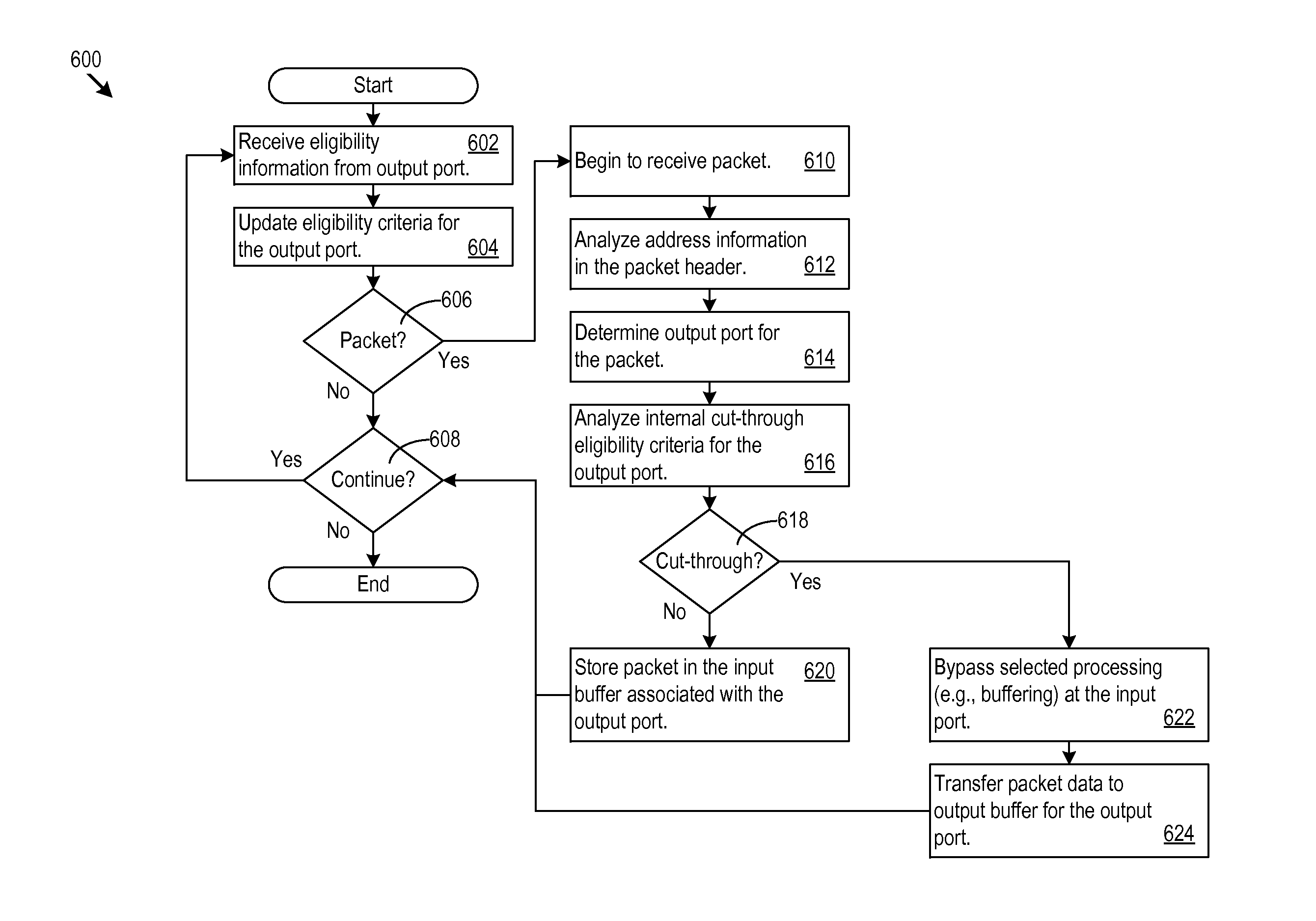
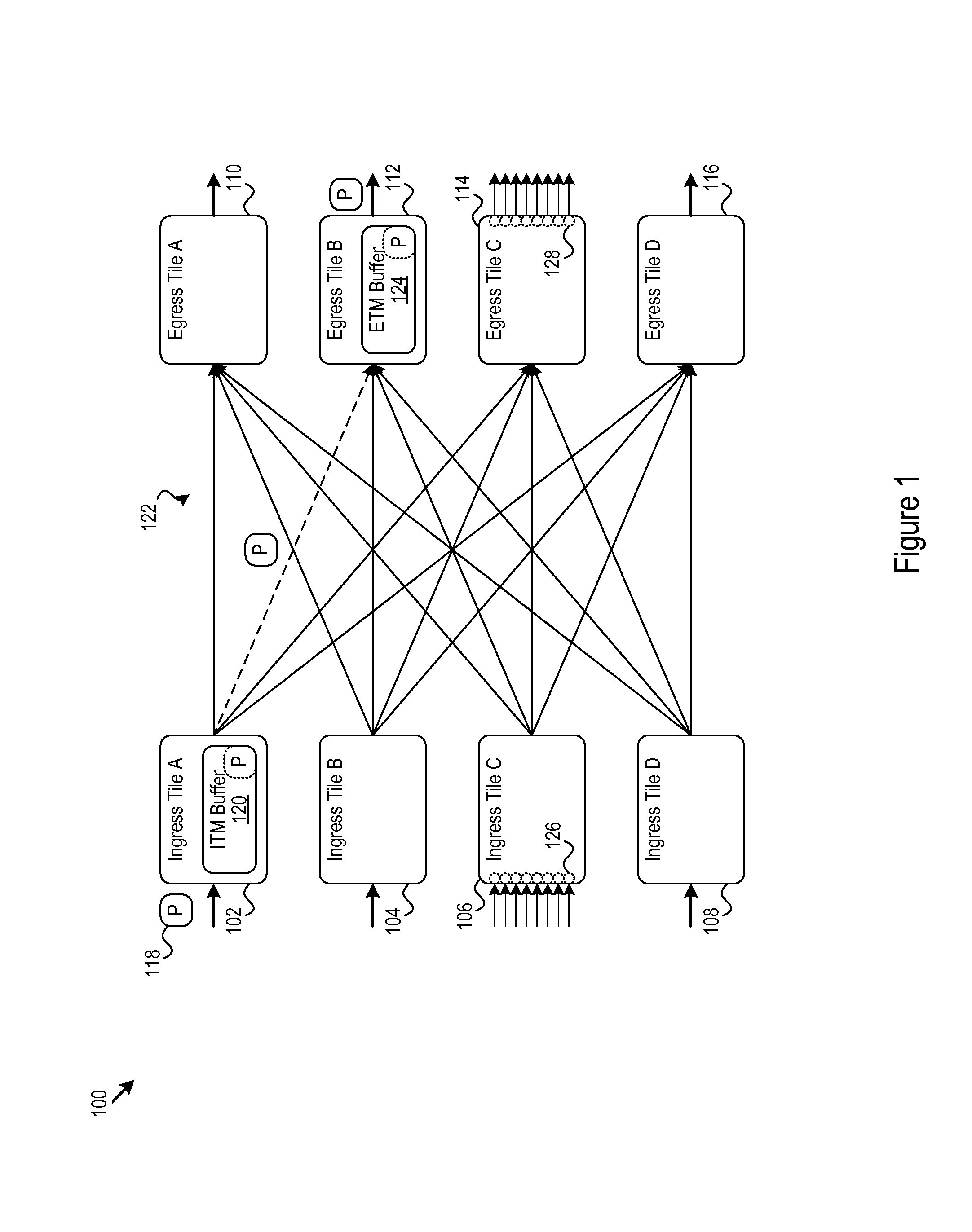
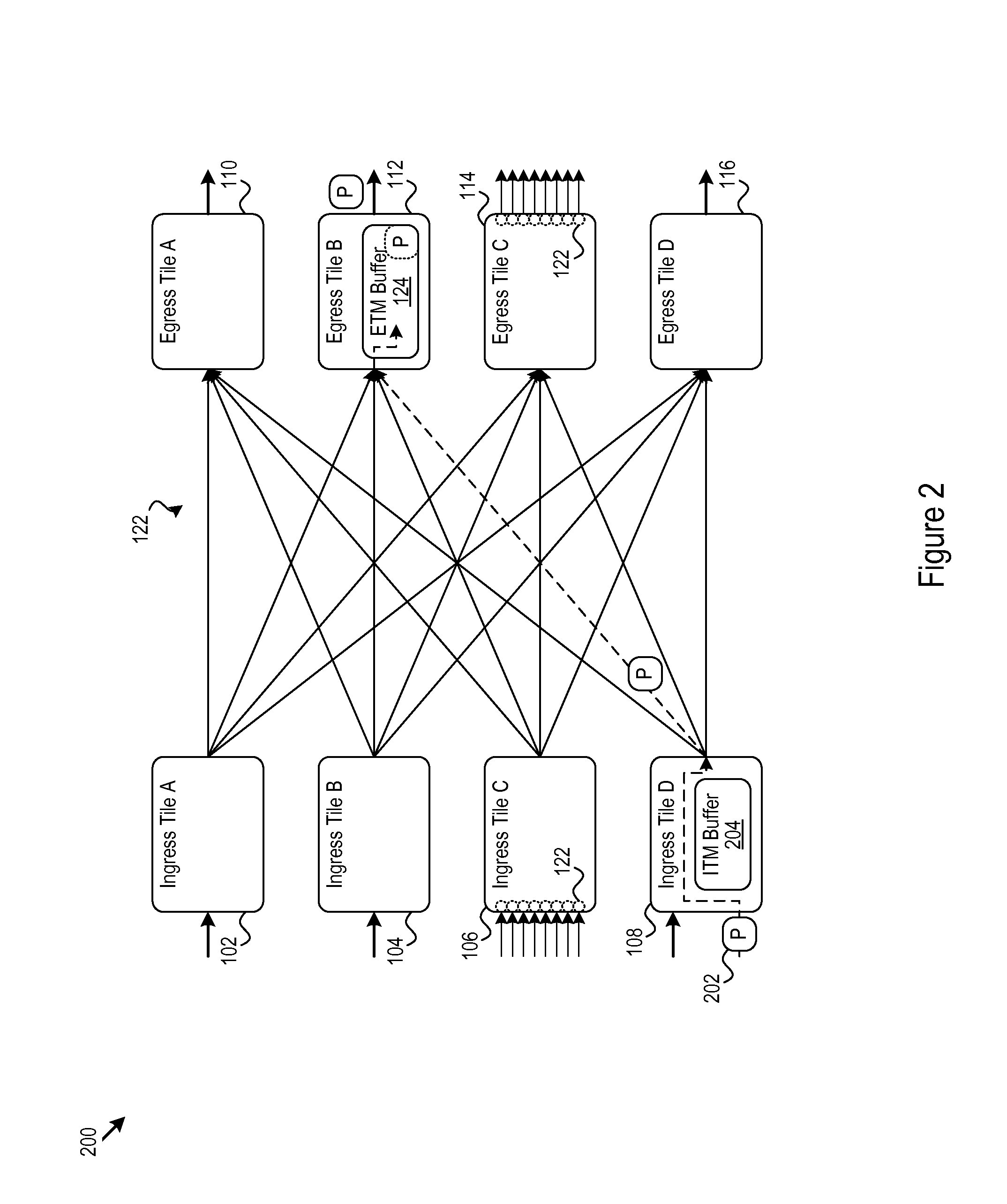
[0011]FIG. 1 shows an example of a switch architecture 100 that switches packets from input ports to output ports. In the example 100, the switch architecture 100 includes several ingress tiles, e.g., the ingress tiles 102, 104, 106, and 108 and several egress tiles, e.g., the egress tiles 110, 112, 114, and 116. A switch fabric 122 connects the ingress tiles 102-108 and the egress tiles 110-116. As shown in FIG. 1, a packet 118 arrives at an input port of the ingress tile A 102 and is buffered in an ingress traffic management (ITM) buffer 120. Under control of the switch architecture 100, the packet 118 flows through the switching fabric 122 and into the egress traffic management (ETM) buffer 124 in the egress tile B 112. The egress tile B 112 sends the packet to a further destination through an output port of the egress tile B 112.

[0012]As will be explained in more detail below, the switch architecture 100 selectively performs internal cut-through of packet data. The internal cut-...


PUM


Abstract

Processing techniques in a network switch help reduce latency in the delivery of data packets to a recipient. The processing techniques include internal cut-through. The internal cut-through may bypass input port buffers by directly forwarding packet data that has been received to an output port. At the output port, the packet data is buffered for processing and communication out of the switch.

Description

PRIORITY CLAIM[0001]This application claims priority to U.S. Provisional Application Ser. No. 61 / 710,222, filed 5 Oct. 2012, which is incorporated herein by reference in its entirety.TECHNICAL FIELD[0002]This disclosure relates networking. This disclosure also relates to reducing latency in communicating packets through networking devices such as switches.BACKGROUND[0003]High speed data networks form part of the backbone of what has become indispensable data connectivity worldwide. Within the data networks, packet switching devices direct data packets from source ports to destination ports, helping to eventually guide the data packets to their correct recipient. In virtually all instances, low latency is desirable for the delivery of the data packets to the recipient. Even when a small percentage of potential recipients are affected by latency issues, the immense number of potential recipients means that a significant number experience the latency issues. Improvements in packet swit...

Claims


Application Information

Patent Timeline
IPC IPC(8): H04L12/56H04L45/74
CPCH04L45/74H04L47/10H04L49/3018H04L49/3027H04L49/506
Inventor MATTHEWS, WILLIAM BRADAGARWAL, PUNEETKWAN, BRUCE HUI
Owner AVAGO TECH INT SALES PTE LTD
Learn More