Electromechanical braking system architecture

a technology of electronic mechanical braking and braking system, applied in aircraft braking arrangements, navigation instruments, instruments, etc., to achieve the effect of improving the accuracy of anti-skid protection functions and reducing the time required

Active Publication Date: 2014-04-10
SAFRAN LANDING SYSTEMS
View PDF5 Cites 23 Cited by
  • Summary
  • Abstract
  • Description
  • Claims
  • Application Information

AI Technical Summary

Benefits of technology

[0014]Thus, the information about speed of rotation does not pass via a data concentrator, thereby serving to reduce the time required for transmitting speed information and improving the accuracy of the anti-skid protection function.

Problems solved by technology

Furthermore, since both controllers are connected to the rotary speed sensor of the wheel, the controller that has not failed can still provide anti-skid protection, and can apply it to the remaining actuators under its control.

Method used


Image

  • Electromechanical braking system architecture
  • Electromechanical braking system architecture

Examples


Embodiment Construction

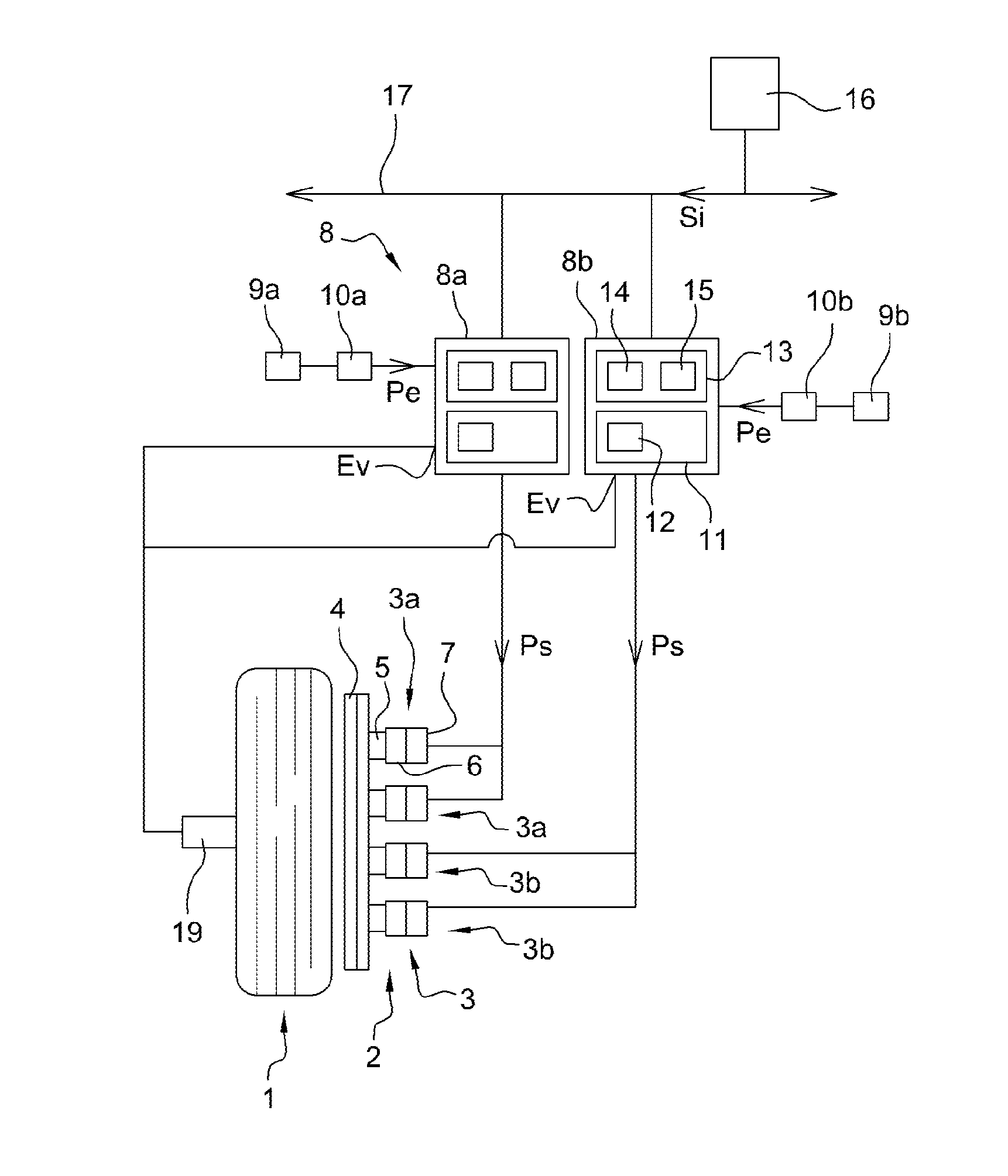
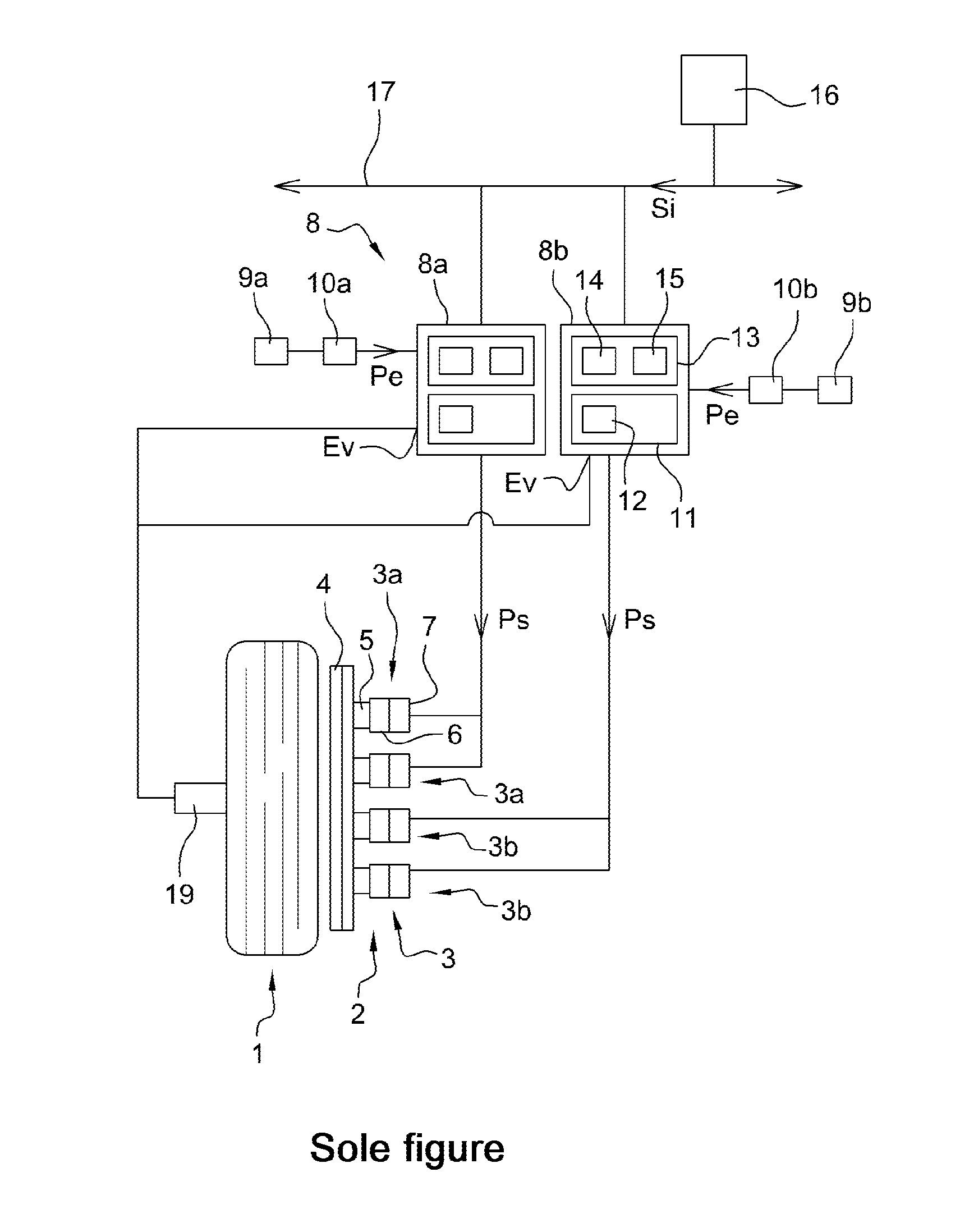
[0016]The brake system architecture of the invention is described below with reference to an aircraft having a plurality of undercarriages fitted with braked wheels similar to the undercarriage shown in the sole FIGURE. Each braked wheel 1 has an electromechanical brake 2 made up in this example of four electromechanical actuators 3, specifically two actuators 3a and two actuators 3b adapted to press selectively against a facing stack of disks 4. Each actuator 3 has a pusher 5 driven by an electric motor 6 and is fitted with a parking blocking member 7 that enables the pusher 5 to be blocked in position when the actuator 3 has been blocked in order to exert a parking force on the disk 4.

[0017]The architecture in this example has two actuator controllers (or EMACs) 8, specifically a first controller 8a and a second controller 8b, each associated with each of the wheels 1, each controller 8 receiving input electric power Pe coming from first and second alternating current (AC) power b...


PUM


Abstract

The invention relates to a braking system architecture for an aircraft having wheels 1 braked by means of respective brakes 2, each brake having a plurality of electromechanical actuators 3a, 3b, the braking system having controllers 8a, 8b for distributing electric power Ps to the actuators 3a, 3b in response to a braking setpoint, each controller 8a, 8b being associated with some of the actuators of any given brake. According to the invention, each controller 8a, 8b has an input Ev for receiving information about the rotary speed of the wheel 1 braked by the actuators associated with said controller, the controller including processor means 13 for modulating the power transmitted to the actuators as a function of the speed of rotation of the wheel in order to provide anti-skid protection.

Description

[0001]The invention relates to an architecture for an aircraft braking system having wheels that are braked by means of brakes having electromechanical actuators.BACKGROUND OF THE INVENTION[0002]Electromechanical aircraft braking system architectures are known, in particular from documents FR 2 964 625 and FR 2 952 009, that include a certain number of actuator controllers (also known as electromechanical actuator controllers or EMACs) and braking computers (or brake system controllers (BSCs), or electronic braking control units (EBCUs), and in which the electromechanical actuators of the brake of each wheel fitted with a brake (i.e. each “braked” wheel) are grouped together in two complementary groups such that a first group of actuators is controlled by a first controller that controls those actuators only, and a second group of actuators is controlled by a second controller that controls those actuators only.[0003]The actuators of each brake are dimensioned so that in the event o...

Claims


Application Information

Patent Timeline
Patent Type & Authority Applications(United States)
IPC IPC(8): B64C25/46
CPCB64C25/46B60T8/1703
Inventor THIBAULT, JULIEN
Owner SAFRAN LANDING SYSTEMS
Why Eureka
Try Eureka