
Pressure Actuated Ported Sub for Subterranean Cement Completions

a technology of actuating sleeve and ported sub, which is applied in the direction of cabinets, well accessories, boreholes/wells, etc., can solve the problems of sleeve sticking, design cannot be used in cementing applications, and leakage potential from tubing to annulus

Active Publication Date: 2014-04-17
BAKER HUGHES INC
View PDF4 Cites 19 Cited by
  • Summary
  • Abstract
  • Description
  • Claims
  • Application Information

AI Technical Summary

Benefits of technology

The patent describes a device that uses a shifting sleeve to create an opposing force to the movement of pressure applied through a differential piston area. The device also has an indexing feature that prevents the sleeve from being biased in the opposite direction when pressure is applied. This allows for controlled fracturing through cement with a lateral port while avoiding damage to the device. The technical effect of the invention is improved precision and control during wellbore construction.

Problems solved by technology

The problem is that to get the lower seal to be smaller than the upper seal to create the desired net force in the needed direction, the wall of the sleeve adjacent the lower seal and the atmospheric chamber has to be reduced so that the sleeve can shift while the volume of the atmospheric chamber is reduced.
When that happens the sleeve gets stuck and the desired port opening in the housing fails to occur.
This design cannot be used in cementing applications as the filling up of the annulus with cement can block access to annulus pressure.
Furthermore, there is a leak path potential from the tubing to the annulus through a piston seal leak.
The application is to prevent fluid loss during treatment and the design is impractical in a cementing application.

Method used


Image

  • Pressure Actuated Ported Sub for Subterranean Cement Completions
  • Pressure Actuated Ported Sub for Subterranean Cement Completions
  • Pressure Actuated Ported Sub for Subterranean Cement Completions

Examples


Embodiment Construction

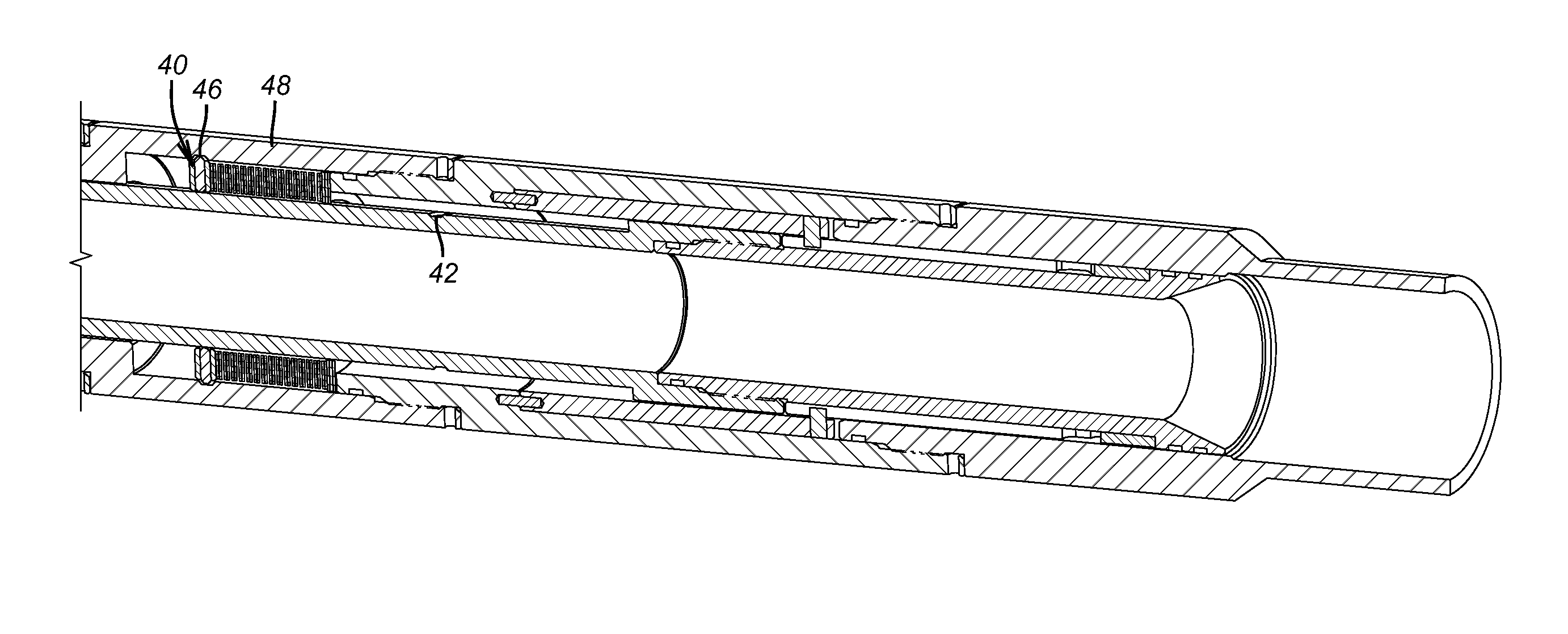
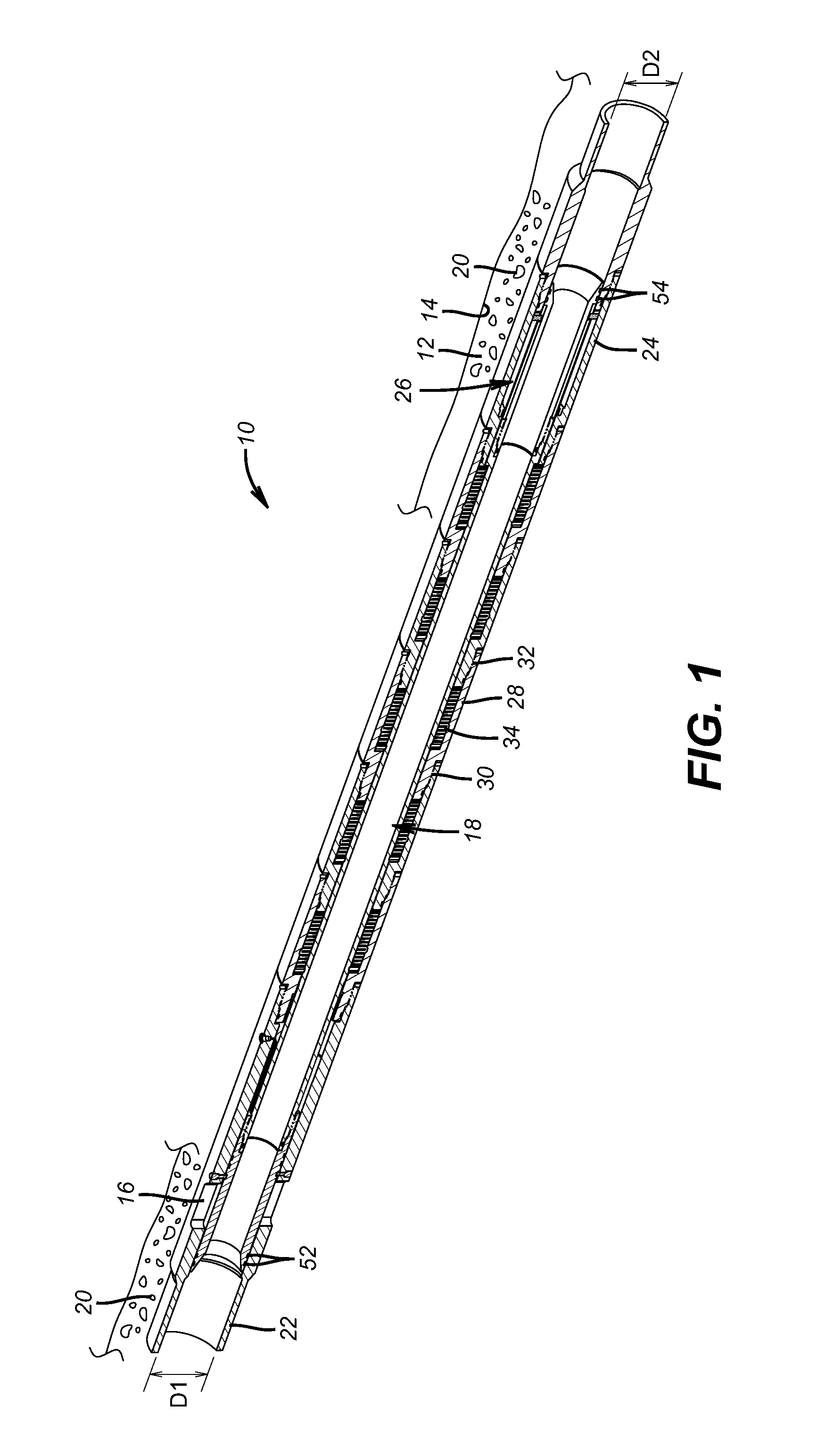
[0020]Referring to FIG. 1 the ported sub 10 is part of a cementing assembly supported on a string that is not shown and leading to a bottom hole assembly (BHA) that has a cementing shoe and landing collars for wiper darts that aid in displacing cement to the surrounding annulus 12 of a borehole 14. When the cementing is done the port or ports 16 can be opened with shifting of sleeve assembly 18 so that the formation can be fractured through the set up cement.

[0021]The sub 10 allows pressure testing the string supporting the sub 10 at a higher pressure than will ultimately be needed to open the ports 16 for a subsequent frac of the formation through the cement 20.

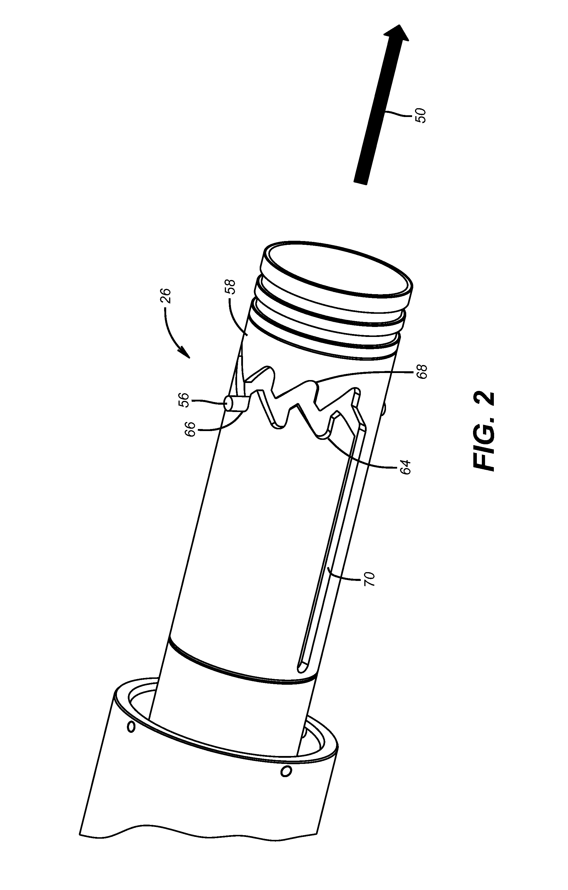
[0022]The ported sub 10 has a top sub 22 and a bottom sub 24. Each of these subs can be in one or more parts secured together generally by being threaded together. The top sub 22 has the ports 16 and the bottom sub 24 houses the indexing assembly 26 as will be explained in more detail below. In between the subs 22 and 24 are...


PUM


Abstract

A shifting sleeve has differential piston areas so that applied pressure displaces the sleeve against spring bias, which preferably is a series of Belleville washer stacks associated with modular mandrel components, to obtain the desired opposing force to the movement initiated with pressure applied to differential piston areas. An indexing feature is located between the sleeve and the mandrel passage wall and on a predetermined number of cycles disables the Belleville washer stacks from biasing the sleeve in an opposed direction as when pressure is applied. At this time the pressure in the mandrel acting on the differential piston area simply shifts the sleeve to open a lateral port so that fracturing through the cement that was earlier placed with the port closed can take place.

Description

FIELD OF THE INVENTION[0001]The field of the invention is a pressure actuated sleeve used in a cementing assembly that is responsive to tubing pressure to open a port and more particularly a sleeve that has differential piston areas where application and removal of pressure cycles the sleeve on a j-slot to allow string pressure testing at a higher pressure than a pressure that releases a bias on the sleeve to allow the differential piston area to shift the sleeve to open a port at a lower pressure than the string integrity testing pressure.BACKGROUND OF THE INVENTION[0002]Prior sleeves that have been deployed in cementing service have been based on the concept of providing opposed piston areas exposed to tubing pressure that are of different dimensions so that raising the tubing pressure will create a sufficient net force to in theory overcome seal friction and move the sleeve to the open position. One such design is the Halliburton Initiator Sliding Sleeve that has a larger upper s...

Claims


Application Information

Patent Timeline
IPC IPC(8): E21B33/12
CPCE21B33/12E21B23/006E21B34/14E21B34/10E21B34/102E21B2200/06
Inventor MAILAND, JASON C.KELLNER, JUSTIN C.SANCHEZ, JAMES S.MADERO, PAULJOHNSON, CHARLES C.PUTCH, ROBERT W.
Owner BAKER HUGHES INC
Learn More