
Bearing for a Motor Vehicle

a technology for motor vehicles and bearings, applied in mechanical devices, mechanical suspensions, transportation and packaging, etc., can solve the problems of reducing affecting the force-travel characteristic of the bearing, and limiting the travel of the radial spring, so as to improve the service life and reduce the service life of the elastomer body. , to achieve the effect of optimally adapting the bearing, reducing the bearing service life, and high degree of freedom

Active Publication Date: 2014-04-17
CONTITECH VIBRATION CONTROL
View PDF3 Cites 6 Cited by
  • Summary
  • Abstract
  • Description
  • Claims
  • Application Information

AI Technical Summary

Benefits of technology

The present invention solves the problem of premature wear and tear on bearings by limiting their tension in the elastomer body and using a soft configuration for the progression of the elastomer material. Additionally, the invention includes a special stop design that makes it easier to insert the plug-in holder and allows for the adjustment of the damping behavior. The elastomer material within the cutout and the surrounding elastomer material can have different properties, resulting in better flexibility and adaptability for a variety of requirements.

Problems solved by technology

However, this air gap reduces the service life of the elastomer body and influences the force-travel characteristic of the bearing.
This is because, as a result of the preload, the radial spring travel which the spring struts permit is limited at least in the direction of tension.
However, it should be noted that the introduction of the stop represents an additional working step which makes the production of the bearing more complicated and thus more expensive.
A disadvantage here is that the plug-in holder and stop are produced in one piece from the same material, for example cast aluminum, in order as a result to save a further production step which would be necessary in order to produce these elements separately and then assemble them.
A further disadvantage is that the overall travel of the spring struts in the tension direction (this overall travel being determined by the spacing of the metal components) is reduced, and the stiffness rises sharply.

Method used


Image

  • Bearing for a Motor Vehicle
  • Bearing for a Motor Vehicle
  • Bearing for a Motor Vehicle

Examples


Embodiment Construction

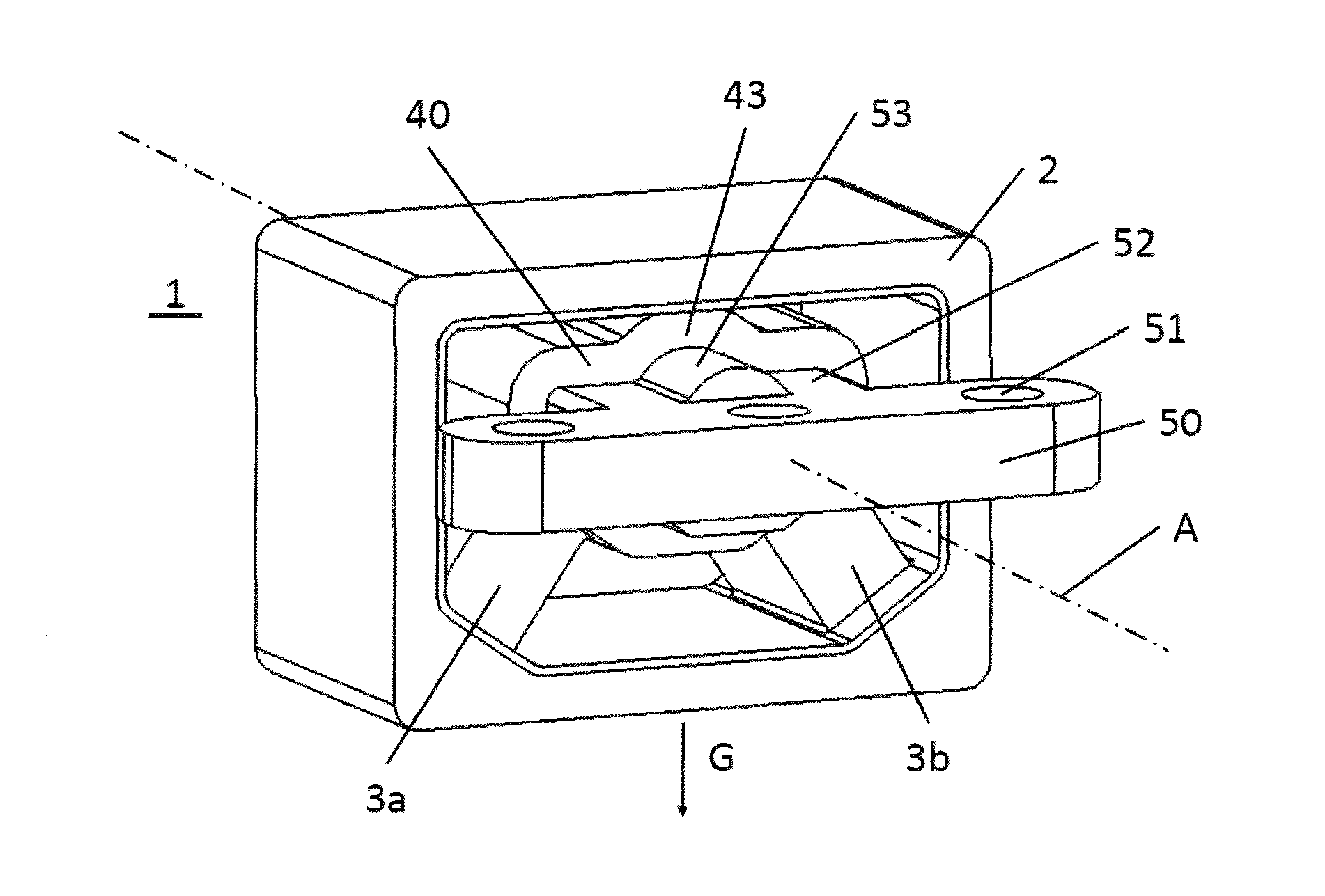
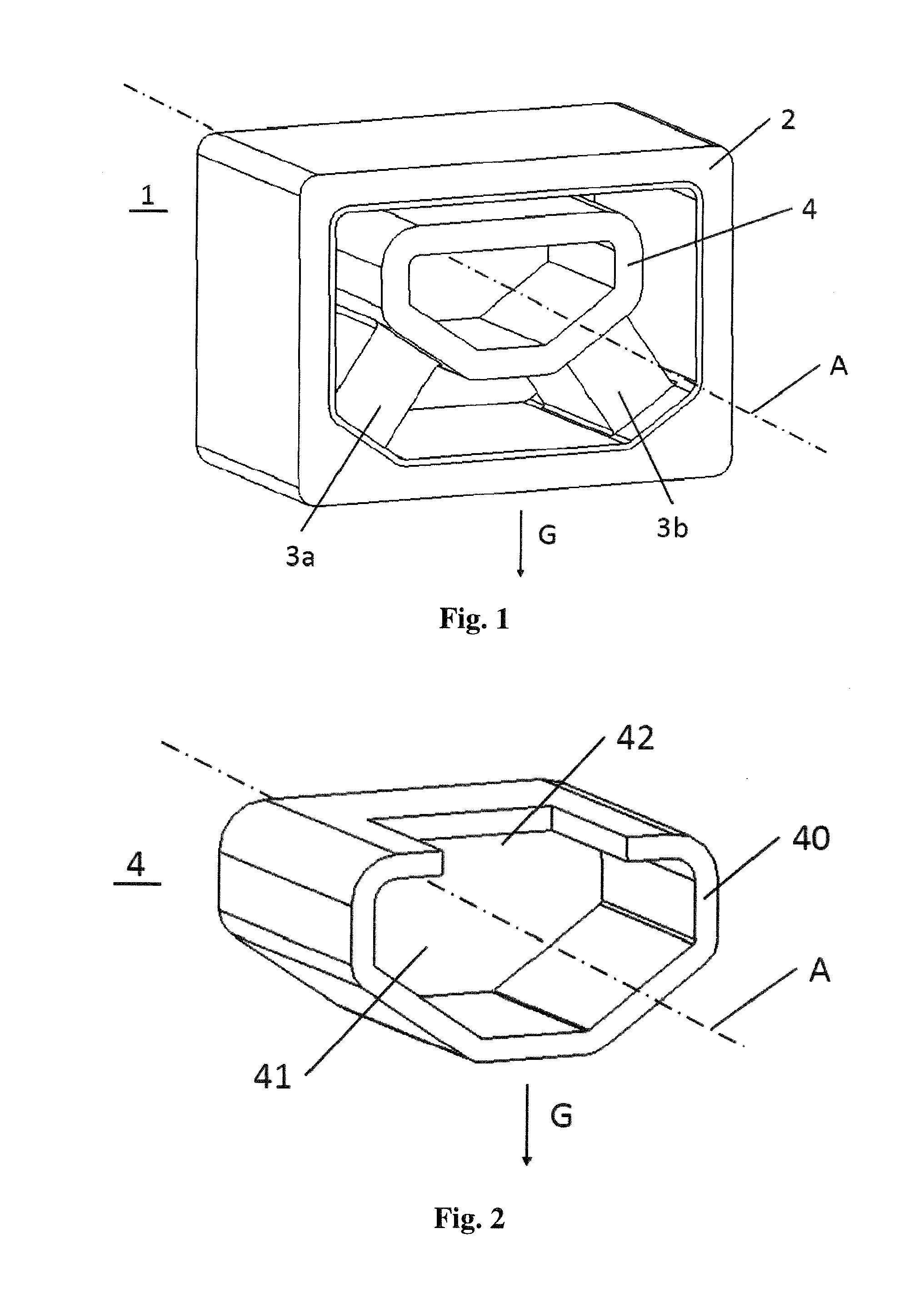
[0031]FIG. 1 shows a perspective schematic of a bearing 1 without plug-in holder 5. The bearing 1 has an outer part 2 which encloses an inner part 4. The two parts (2, 4) are oriented axially along the longitudinal axis A and spaced apart from one another radially, that is, in the plane perpendicular to the longitudinal axis A. In the case of a bearing 1 mounted in a motor vehicle, the longitudinal axis A is oriented substantially perpendicularly to the direction of the weight force G. The two parts (2, 4) have a hexagonal contour in this embodiment. However, it is also possible to use inner parts 4 and outer parts 2 having cylindrical, oval, rectangular or other polygonal contours.

[0032]Provided between the inner part 4 and the outer part 2 are two spring struts (3a, 3b) which connect the inner part 4 and the outer part 2 together in a resilient manner. Alternatively, it may also be possible to provide only one spring strut (not illustrated) which would then be provided preferably ...


PUM

PropertyMeasurementUnit
Forceaaaaaaaaaa
Elastomericaaaaaaaaaa
Hardnessaaaaaaaaaa

Abstract

A bearing for a motor vehicle has an inner part and an outer part which surrounds the inner part. An elastomer body connects the inner part and the outer part to one another by at least one spring leg which is provided substantially below the inner part in the direction of the weight force (G). A plug-in holder is at least partially received by the inner part. The inner part has a cutout on one side filled at least in some regions with an elastomer material. The plug-in holder has a stop opposite the cutout. The stop presses the elastomer material of the cutout against the outer part.

Description

CROSS REFERENCE TO RELATED APPLICATIONS[0001]This application is a continuation application of international patent application PCT / EP2012 / 059940, filed May 29, 2012, designating the United States and claiming priority from German application 10 2011 051 069.9, filed Jun. 15, 2011, and the entire content of both applications is incorporated herein by reference.FIELD OF THE INVENTION[0002]The invention relates to a bearing for a motor vehicle, having an inner part, an outer part which surrounds the inner part, an elastomer body which connects the inner part and the outer part together via at least one spring strut which is provided substantially below the inner part in the direction of the weight force, and a plug-in holder which is provided to be received at least partially by the inner part.BACKGROUND OF THE INVENTION[0003]Bearings of this type are already known from the prior art and are used in a motor vehicle, for example, for mounting the engine. Usually, the outer part is form...

Claims


Application Information

Patent Timeline
IPC IPC(8): F16F1/38
CPCF16F1/3828F16F1/38F16F1/373F16F1/3849
Inventor FIRLA, ANDREAS
Owner CONTITECH VIBRATION CONTROL
Learn More