This helps you quickly interpret patents by identifying the three key elements:
Problems solved by technology
Method used
Benefits of technology
Benefits of technology
The technical effects of this patent are to provide a coaxial connector that reduces components, manufacturing cost, and assembly steps while achieving miniaturization. Additionally, a connector unit is provided that includes this coaxial connector.
Problems solved by technology
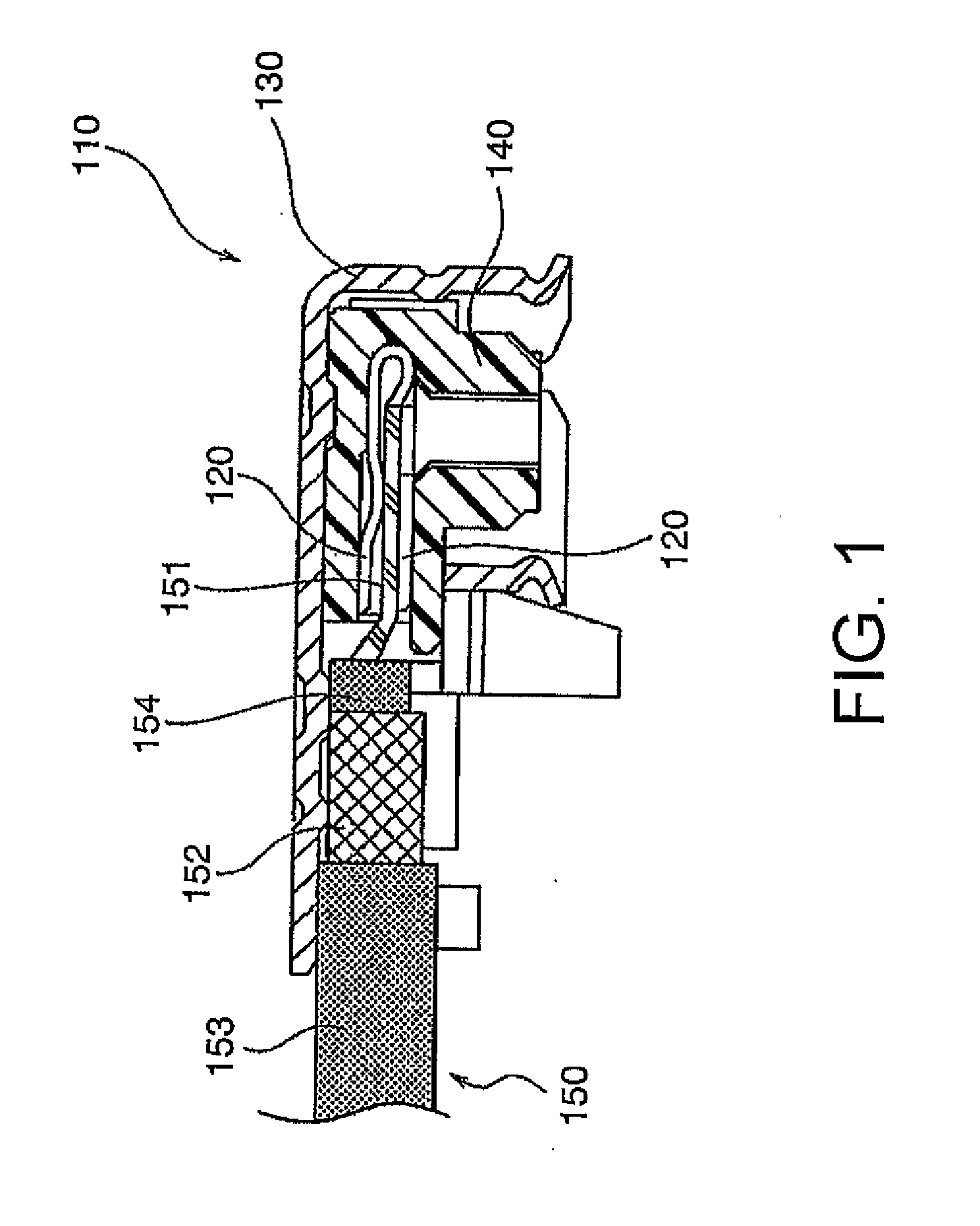
With the coaxial connector 110 of JP-A-2002-324636, however, there has been a problem that when connecting the coaxial cable 150 to the coaxial connector 110, the connecting operation of the outer conductor (shield wire) 152 of the coaxial cable 150 is complicated, thus leading to an increase in the number of assembly steps.
Further, with the coaxial connector 110 of JP-A-2002-324636, there has been a problem that since the connection terminal 120 for contact with a mating contact (not illustrated) of a mating connector (not illustrated) is provided, the number of components increases corresponding to this connection terminal 120, thus leading to an increase in the manufacturing cost of the coaxial connector 110 and hindering the miniaturization of the coaxial connector 110.
Method used
Image
Click on the blue label to locate the original text in one second.
Reading with bidirectional positioning of images and text.
Examples
first embodiment
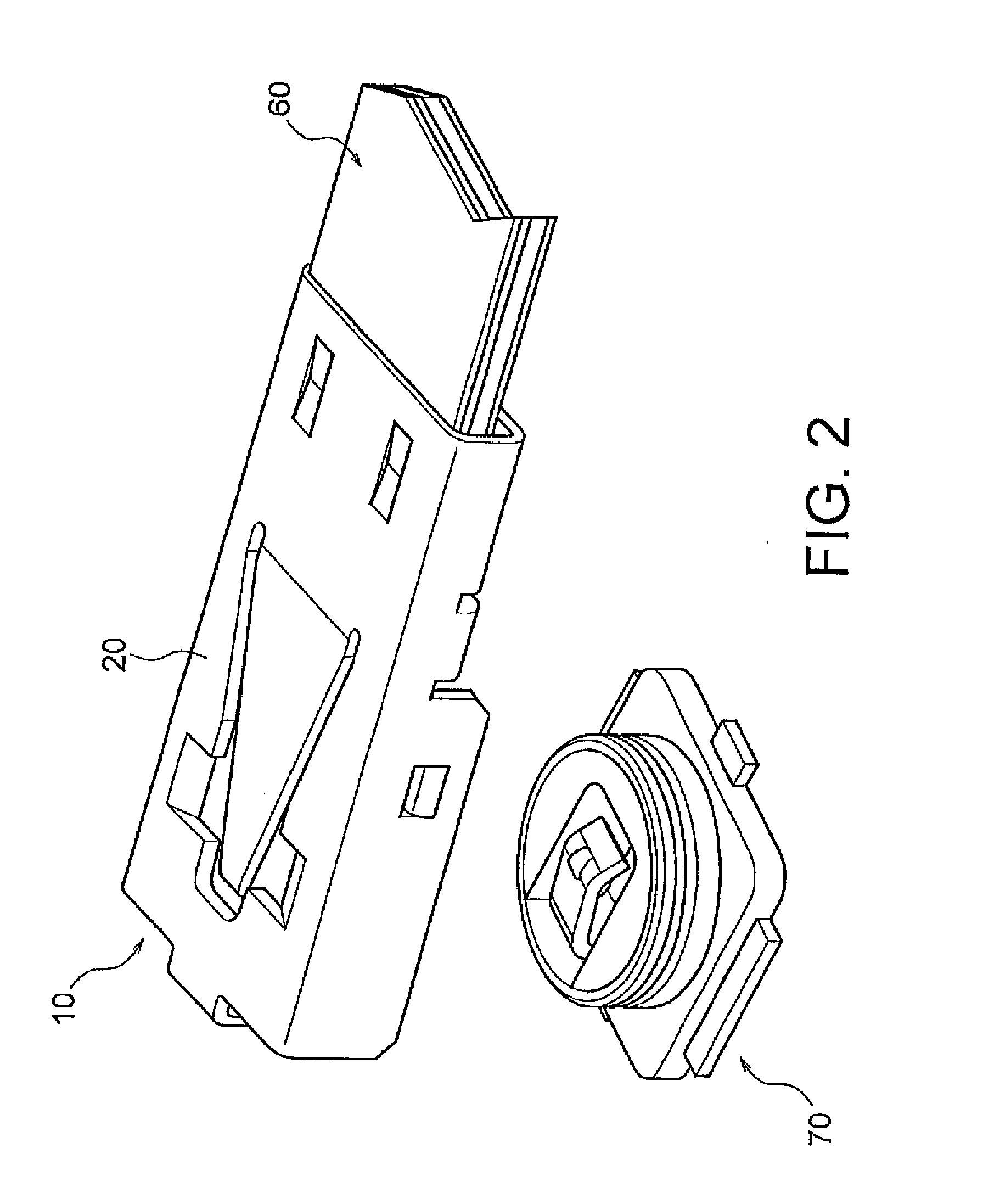
[0022]As shown in FIG. 2, while holding an FPC (flexible printed circuit) 60 as a connection object, a coaxial connector 10 according to this invention is adapted to be fitted to a mating connector 70, thereby achieving electrical connection between the FPC 60 and the mating connector 70.
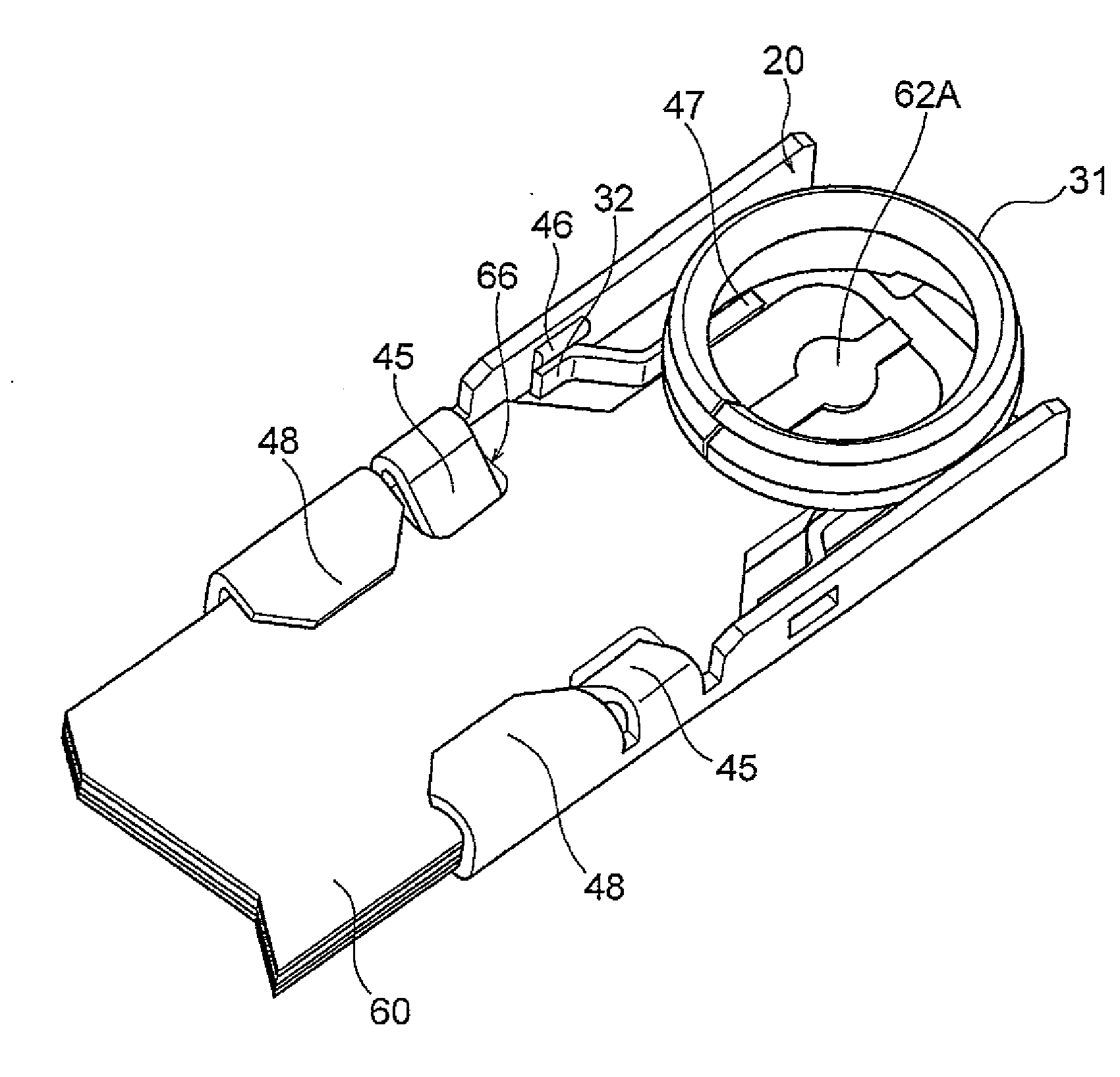
[0023]As shown in FIGS. 2 and 3, the coaxial connector 10 comprises a conductive shell 20 for holding the FPC 60.
[0024]The shell 20 is formed of a conductive metal and, as shown in FIG. 5, comprises a first shell portion 30, a second shell portion 40, and a coupling portion 50 coupling together the first shell portion 30 and the second shell portion 40, which are integrally formed together.
[0025]As shown in FIG. 5, the first shell portion 30 of the shell 20 has a barrel-shaped shell contact portion 31 for contact with a mating shell 72 (see FIG. 7) of the mating connector 70 and a pair of first locking portions 32 for fixing the first shell portion 30 to the second shell portion 40.
[0026]As shown in...
second embodiment
[0064]Further, in the second embodiment, as shown in FIGS. 10 and 11, the second shell portion 40 of the shell 20 has a body portion 41, a pair of side wall portions 42, a first spring portion 43, and the pair of fixing portions 48′. As shown in FIG. 11, the fixing portions 48′ are caulked after the FPC 60 is sandwiched between the first shell portion 30 and the second shell portion 40 so that the free end sides of the fixing portions 48′ cover the frame portion 33 of the first shell portion 30, thereby fixing together the first shell portion 30 and the second shell portion 40 to fix the FPC 60 to the shell 20.
[0065]Also in the second embodiment, as shown in FIG. 10, a coupling portion 50 coupling together the first shell portion 30 and the second shell portion 40 is provided so that the shell 20 is integrally formed as in the first embodiment.
[0066]In the second embodiment, the first spring portion 43 and a portion, denoted by symbol 41A in FIG. 10, of the body portion 41 serve as ...
PUM
Abstract
A coaxial connector is adapted to hold a connection object having a ground conductor and a signal conductor and is adapted to be fitted to a mating connector. The coaxial connector has a shell for holding the connection object. The shell comprises a first shell portion having a barrel-shaped shell contact portion, a second shell portion having shell connecting portions, positioning portions for positioning the connection object so that a contact portion of the signal conductor of the connection object is located inside the barrel-shaped shell contact portion as seen in a fitting direction of the coaxial connector and the mating connector, and fixing portions for fixing the connection object.
Description
[0001]This application is based upon and claims the benefit of priority from Japanese patent application No. 2012-229921, filed on Oct. 17, 2012, the disclosure of which is incorporated herein in its entirety by reference.BACKGROUND OF THE INVENTION[0002]1. Field of the Invention[0003]This invention relates to a coaxial connector and a connector unit and in particular, relates to a coaxial connector that can be used for connecting a connection object having a flat plate portion.[0004]2. Description of Related Art[0005]As shown in FIG. 1, there is known a coaxial connector 110 comprising a connection terminal 120 adapted to be connected to an inner conductor 151 of a coaxial cable 150, a metal shell 130 adapted to be connected to an outer conductor 152 of the coaxial cable 150, and an insulating portion 140 interposed between the connection terminal 120 and the shell 130 (see, e.g. JP-A-2002-324636). In FIG. 1, numeral 153 denotes an outer jacket of the coaxial cable 150 while numera...
Claims
Application Information
Patent Timeline
Application Date:The date an application was filed.
Publication Date:The date a patent or application was officially published.
First Publication Date:The earliest publication date of a patent with the same application number.
Issue Date:Publication date of the patent grant document.
PCT Entry Date:The Entry date of PCT National Phase.
Estimated Expiry Date:The statutory expiry date of a patent right according to the Patent Law, and it is the longest term of protection that the patent right can achieve without the termination of the patent right due to other reasons(Term extension factor has been taken into account ).
Invalid Date:Actual expiry date is based on effective date or publication date of legal transaction data of invalid patent.

