Integration between 3D maps and fluoroscopic images

Active Publication Date: 2014-04-24
BIOSENSE WEBSTER (ISRAEL) LTD
View PDF13 Cites 36 Cited by
  • Summary
  • Abstract
  • Description
  • Claims
  • Application Information

AI Technical Summary

Benefits of technology

[0036]configuring one or more connectors to receive magnetic sensors in respective predetermined fixed locations and orientations with respect to the jig, so that signals from the ma

Problems solved by technology

Because of the lack of automatic registration and coordination between the fluoroscopic and 3D views, the physician is required to

Method used


Image

  • Integration between 3D maps and fluoroscopic images
  • Integration between 3D maps and fluoroscopic images
  • Integration between 3D maps and fluoroscopic images

Examples


Embodiment Construction

[0046]In the following description, like elements in the drawings are identified by like numerals, and the like elements are differentiated as necessary by appending a letter to the identifying numeral.

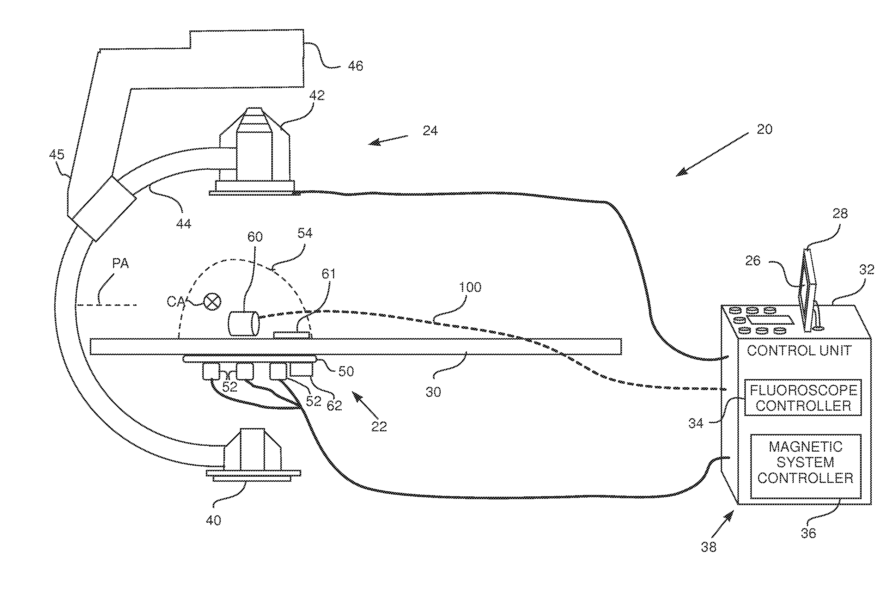
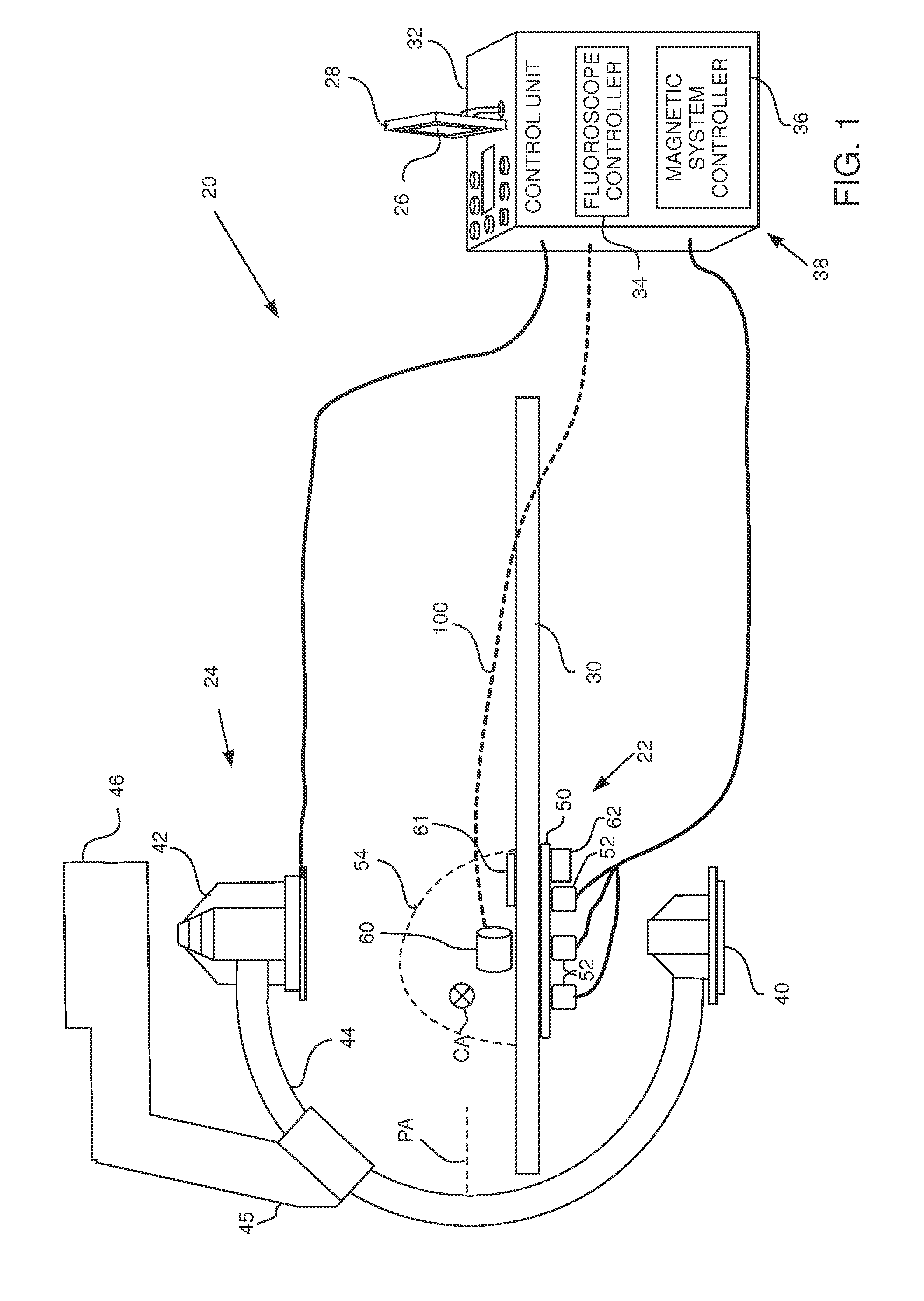
[0047]FIG. 1 is a schematic diagram illustrating a fluoroscopic image and magnetic mapping integration system 20 in a calibration phase, according to an embodiment of the present invention. System 20 combines a three-dimensional (3D) map of a body organ that is acquired by a magnetic tracking system 22, with a two-dimensional (2D) fluoroscopic image of the patient acquired by a fluoroscope 24, so forming a combined display 26 that is presented to an operator of system 20 on a screen 28. In the calibration phase for system 20 illustrated in FIG. 1 the patient is not present. In a subsequent operational phase of system 20, illustrated in FIG. 5, the patient is assumed to be lying on a table 30 of system 20, and magnetic tracking system 22 and fluoroscope 24 acquire the 3D map and 2D ima...


PUM


Abstract

A coordinate system registration module, including radiopaque elements arranged in a fixed predetermined pattern and configured, in response to the radiopaque elements generating a fluoroscopic image, to define a position of the module in a fluoroscopic coordinate system of reference. The module further includes one or more connections configured to fixedly connect the module to a magnetic field transmission pad at a predetermined location and orientation with respect to the pad, so as to characterize the position of the registration module in a magnetic coordinate system of reference defined by the magnetic field transmission pad.

Description

CROSS-REFERENCE TO RELATED APPLICATION[0001]This application claims the benefit of U.S. Provisional Patent Application 61 / 715,935 filed 19 Oct. 2012, which is incorporated herein by reference.FIELD OF THE INVENTION[0002]The present invention relates generally to combining images, and specifically to combining a two-dimensional fluoroscope image with a three-dimensional map.BACKGROUND OF THE INVENTION[0003]In current cardiac catheterization systems, the operating physician must often observe two different images simultaneously, on two different screens: 2D fluoroscopic images of the thorax and 3D maps of the heart. Such 3D maps may be generated, for example, using magnetic tracking of the catheter tip in the heart. Both the fluoroscopic images and the 3D maps may show the catheter, but from different angles and perspectives. Because of the lack of automatic registration and coordination between the fluoroscopic and 3D views, the physician is required to switch his or her attention ba...

Claims


Application Information

Patent Timeline
IPC IPC(8): A61B6/00A61B6/02A61B5/05A61B5/00A61B5/06A61M25/01
CPCA61B6/5247A61B5/0035A61B5/0522A61B5/062A61B5/7425A61B6/02A61M25/0127A61B6/4441A61B6/463A61B6/485A61B6/54A61M25/0108A61B6/4417A61B2090/364A61B2090/376A61B90/37A61B2034/2051A61B2090/3954A61B2090/3966
Inventor BAR-TAL, MEIRDEMRI, TAMIRZINO, ELIAHUGLAZER, RANZIGELMAN, GILBERMAN, DROR
Owner BIOSENSE WEBSTER (ISRAEL) LTD
Why Eureka
Try Eureka