
Smart camera

a smart camera and camera body technology, applied in the field of machine control systems, can solve the problems of increasing the cost and size of motors which must be used, increasing the weight of cables which must be routed to various moving parts, and increasing the inertia of moving parts

Inactive Publication Date: 2006-01-17
ORMON CORP
View PDF49 Cites 74 Cited by
  • Summary
  • Abstract
  • Description
  • Claims
  • Application Information

AI Technical Summary

Benefits of technology

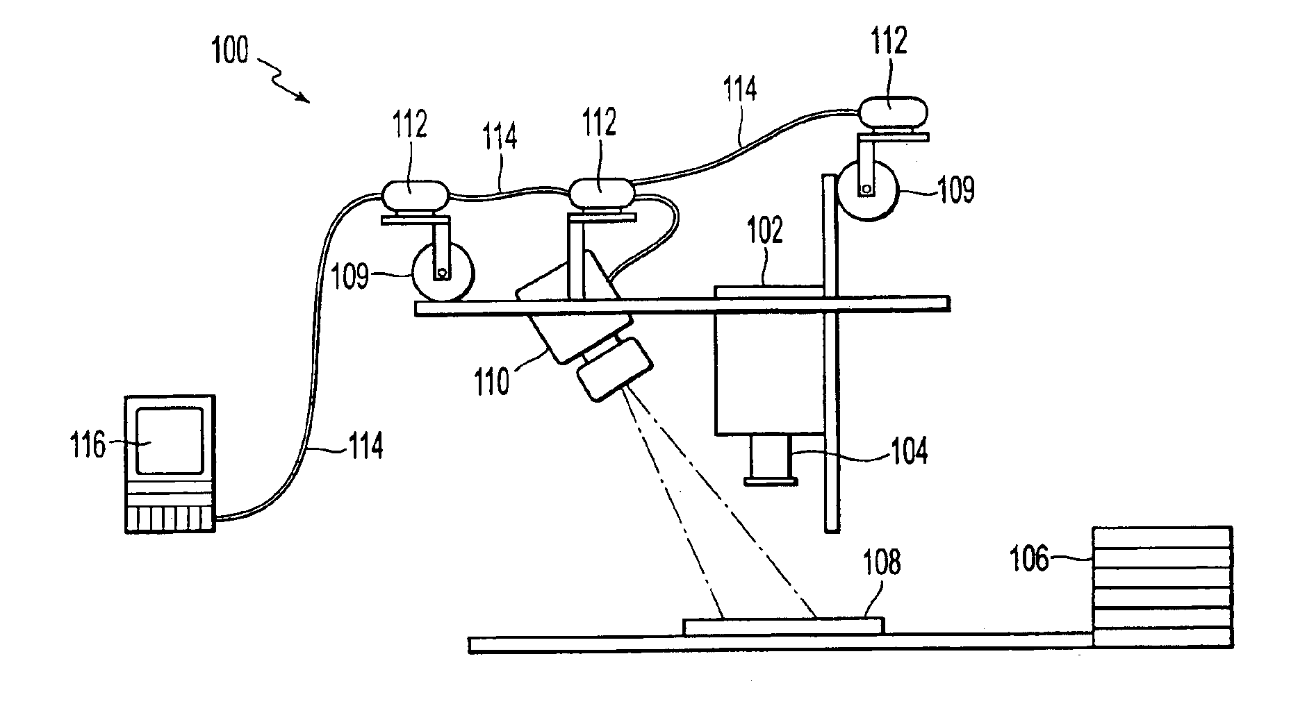
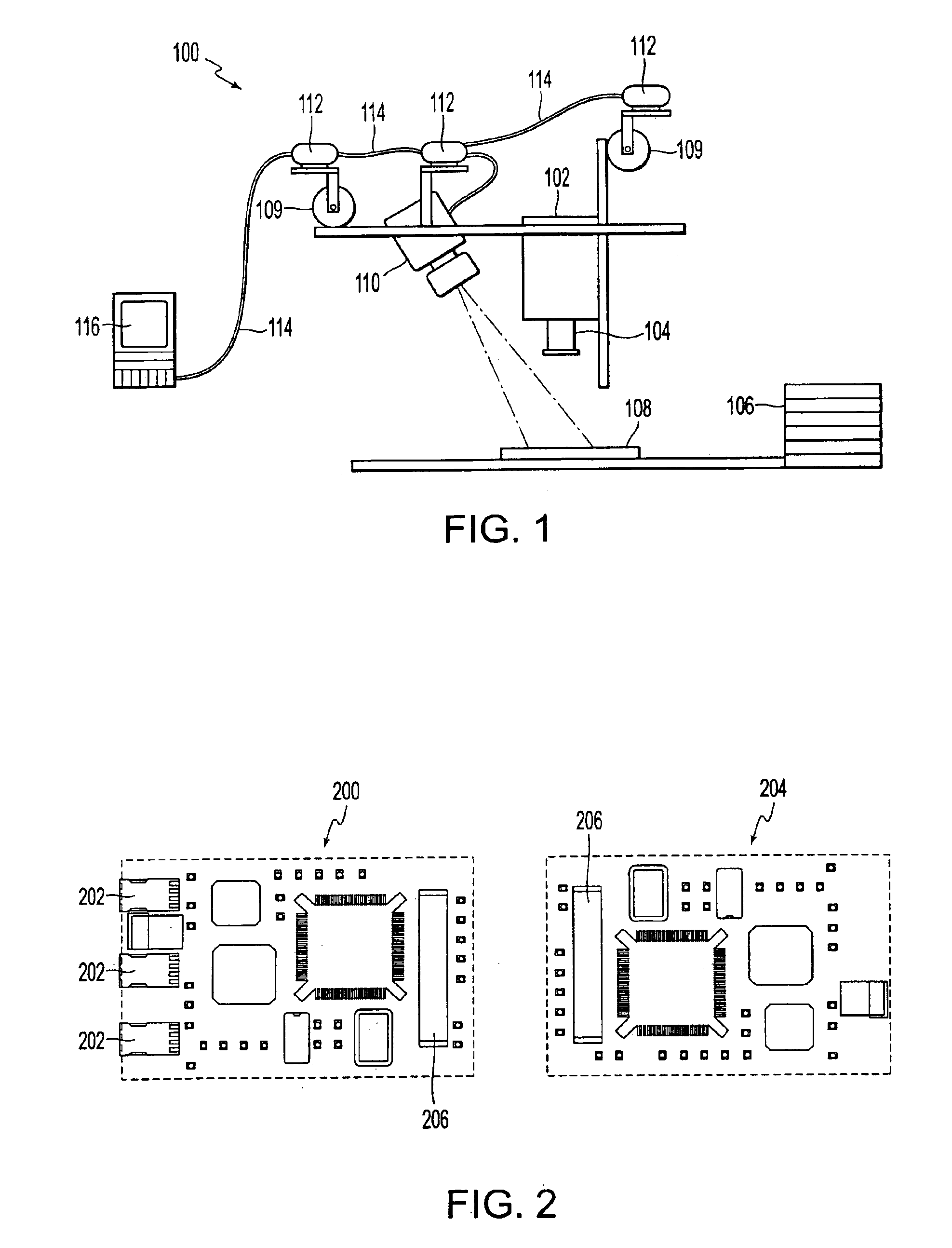
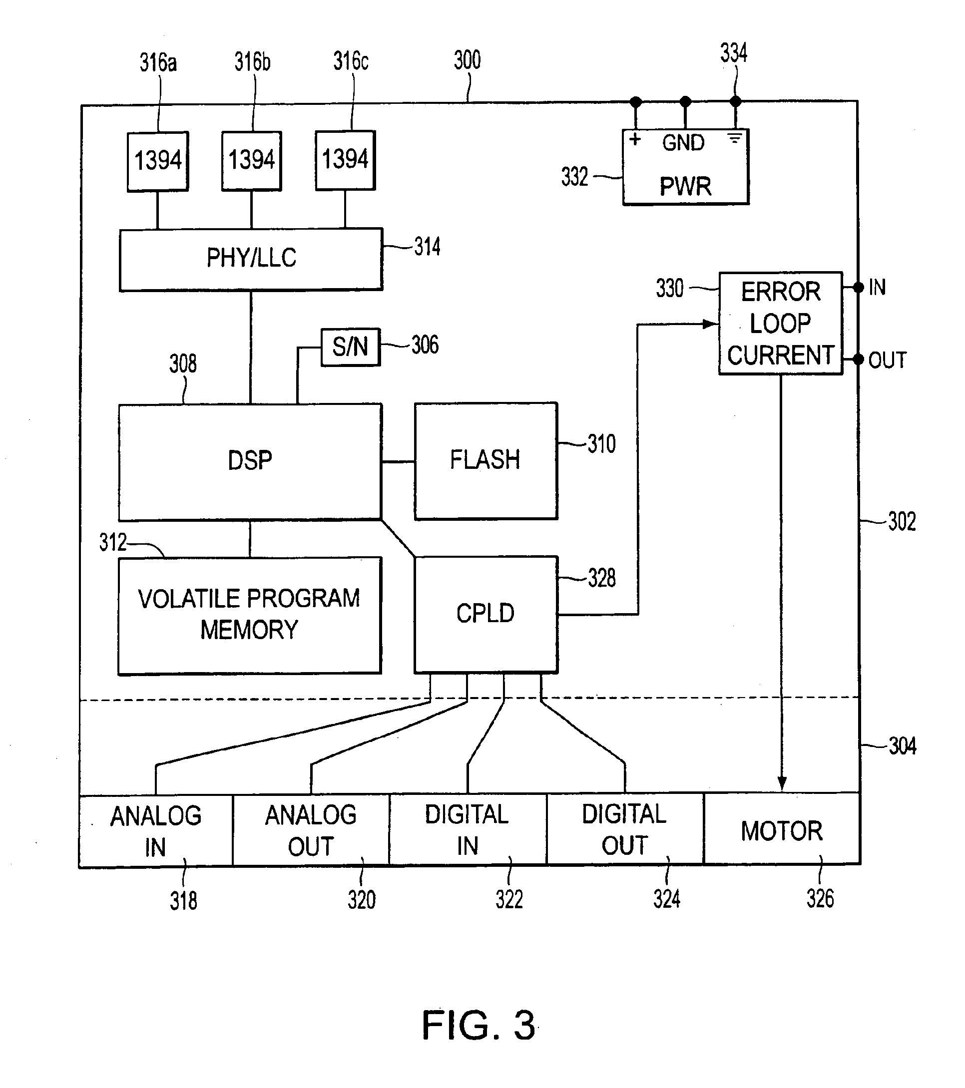
[0005]A smart camera system provides focused images to an operator at a host computer by processing digital images at the imaging location prior to sending them to the host computer. The smart camera has a resident digital signal processor for preprocessing digital images prior to transmitting the images to the host. The preprocessing includes image feature extraction and filtering, convolution and deconvolution methods, correction of parallax and perspective image error and image compression. Compression of the digital images in the smart camera at the imaging location permits the transmission of very high resolution color or high resolution grayscale images at real-time frame rates such as 30 frames per second over a high speed serial bus to a host computer or to any other node on the network, including any remote address on the Internet.

Problems solved by technology

The result is that with complex systems, the cables which must be routed to various moving parts can be complex, heavy and take up large volumes.
For moving parts, added weight increases the cost and size of motors which must be used to achieve a given function.
In complex assembly equipment, added weight adds inertia to moving parts which must be precisely located rendering that task more difficult.

Method used


Image

  • Smart camera
  • Smart camera
  • Smart camera

Examples


Embodiment Construction

[0014]Embodiments of the present invention are described herein in the context of a smart camera. Those of ordinary skill in the art will realize that the following detailed description of the present invention is illustrative only and is not intended to be in any way limiting. Other embodiments of the present invention will readily suggest themselves to such skilled persons having the benefit of this disclosure. Reference will now be made in detail to implementations of the present invention as illustrated in the accompanying drawings. The same reference indicators will be used throughout the drawings and the following detailed description to refer to the same or like parts.

[0015]In the interest of clarity, not all of the routine features of the implementations described herein are shown and described. It will, of course, be appreciated that in the development of any such actual implementation, numerous implementation-specific decisions must be made in order to achieve the develope...


PUM


Abstract

A smart camera system provides focused images to an operator at a host computer by processing digital images at the imaging location prior to sending them to the host computer. The smart camera has a resident digital signal processor for preprocessing digital images prior to transmitting the images to the host. The preprocessing includes image feature extraction and filtering, convolution and deconvolution methods, correction of parallax and perspective image error and image compression. Compression of the digital images in the smart camera at the imaging location permits the transmission of very high resolution color or high resolution grayscale images at real-time frame rates such as 30 frames per second over a high speed serial bus to a host computer or to any other node on the network, including any remote address on the Internet.

Description

RELATED APPLICATIONS[0001]This application is related to and claims the benefit of: (1) provisional U.S. Patent Application Ser. No. 60 / 188,562 filed on Mar. 10, 2000 in the name of Edison T. Hudson, entitled “Smart camera”, commonly assigned herewith; (2) provisional U.S. Patent Application Ser. No. 60 / 188,580 filed on Mar. 10, 2000 in the names of Edison T. Hudson, James McCormick, Ronald G. Genise and Jerome Dahl, entitled “Hardware architecture and method for distributed machine control”, commonly assigned herewith; and is a continuation-in-part of (3) U.S. Non-Provisional patent application Ser. No. 09 / 779,913 filed Feb. 7, 2001 in the names of Edison T. Hudson, James McCormick, Ronald G. Genise and Jerome Dahl, entitled “Hardware architecture and method for distributed machine control”, commonly assigned herewith.FIELD OF THE INVENTION[0002]The present invention relates to machine control systems. The invention has broad applicability to machine systems requiring controllers w...

Claims


Application Information

Patent Timeline
Patent Type & Authority Patents(United States)
IPC IPC(8): G01B15/00G05B19/042
CPCG05B19/0421G05B2219/39391G05B2219/23298G05B2219/23304G05B2219/25032G05B2219/25072G05B2219/25144G05B2219/25166G05B2219/25178G05B2219/25217G05B2219/25234G05B2219/25308G05B2219/2651G05B2219/34012G05B2219/37494G05B2219/37555G05B2219/21053
Inventor HUDSON, EDISON T.MCCORMICK, JAMESGENISE, RONALD G.DAHL, JEROME
Owner ORMON CORP
Learn More