
Fixing member manufacturing method and fixing member manufacturing apparatus

Active Publication Date: 2014-05-01
CANON KK
View PDF0 Cites 5 Cited by
  • Summary
  • Abstract
  • Description
  • Claims
  • Application Information

AI Technical Summary

Benefits of technology

The present invention provides a method and apparatus for manufacturing a fixing member that can perform its fixing duties effectively for an extended period of time.

Problems solved by technology

However, there is a fear that a fixing member manufactured by coating a cylindrical elastic layer with the thin fluorine-containing resin tube formed by the extrusion molding and then by fixing the elastic layer and the tube with an adhesive generates cracks, with respect to a longitudinal direction of the fluorine-containing resin tube, with an increase in the number of sheets subjected to the fixing.
However, the fluorine-containing resin tube has manufacturing variation, and therefore when the fluorine-containing resin tube having a small diameter was increased in diameter, non-negligible plastic deformation was generated in some cases.
At a portion where the plastic deformation is generated, even when heating in a subsequent step is made, there is a fear that flex resistance (elasticity) and crack resistance are lowered due to a decrease in thickness of the fluorine-containing resin tube compared with a portion where the plastic deformation is not generated and due to residual stress.

Method used


Image

  • Fixing member manufacturing method and fixing member manufacturing  apparatus
  • Fixing member manufacturing method and fixing member manufacturing  apparatus
  • Fixing member manufacturing method and fixing member manufacturing  apparatus

Examples


embodiment 1

[0132]Embodiment 1 will be described. Constituent elements (members) identical in constitution to those in Embodiment 1 are represented by the same reference numerals or symbols as those in Embodiment 1 and will be omitted from detailed description. In this embodiment, the fixing belt manufacturing method in Embodiment 1 is applied to a pressing belt manufacturing method.

(1) Pressing Belt 30

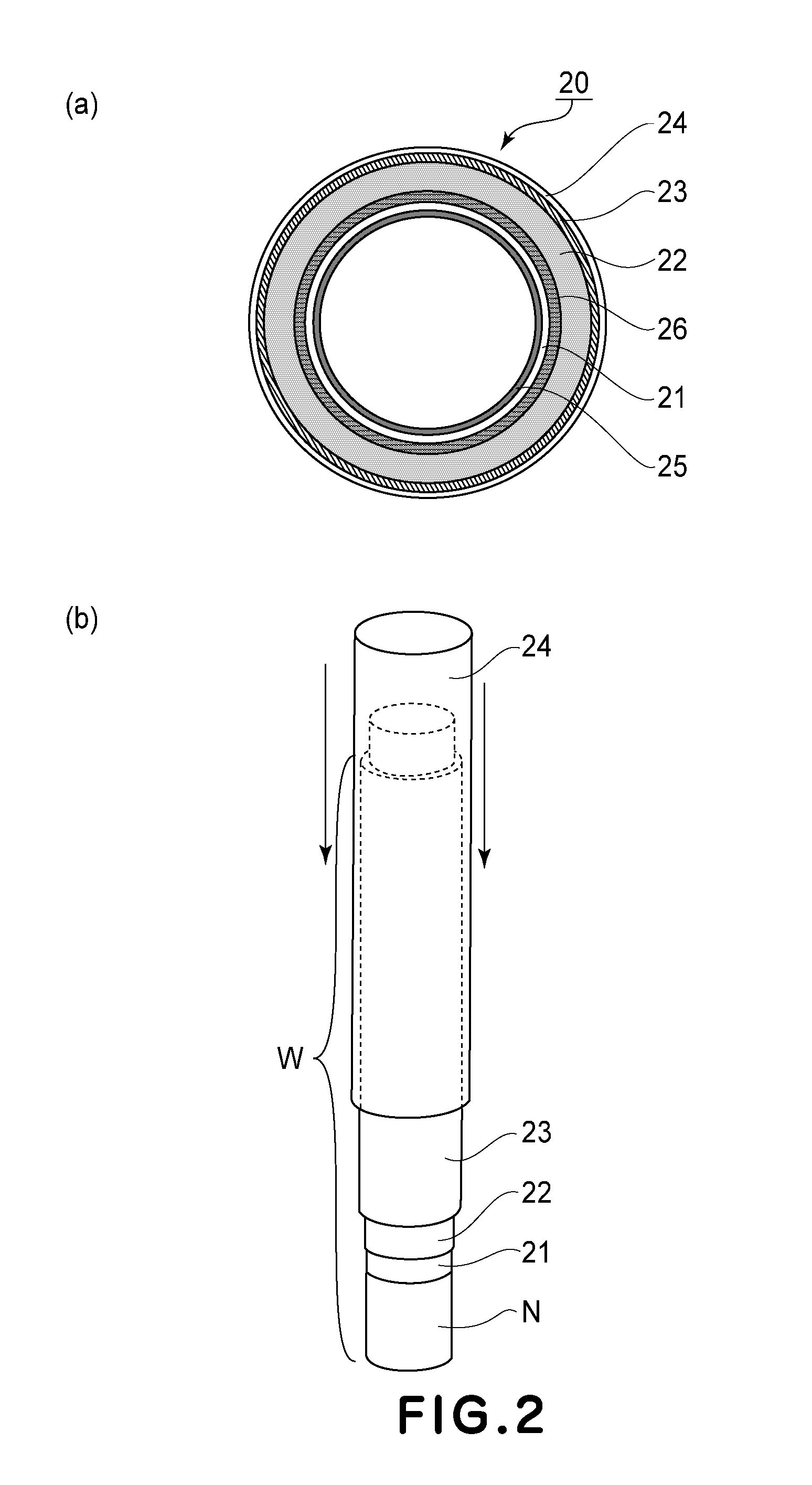
[0133]In this embodiment, with respect to also a layer structure of the pressing belt 30, as the other fixing member, opposing the fixing belt 20, the same layer structure as that of the fixing belt 20 was employed. That is, similarly as in the layer structure of the fixing belt 20 shown in FIG. 2. The layer structure of the pressing belt 30 includes the base material 21, the elastic layer 22, the adhesive layer 23, the fluorine-containing resin tube 24 and the like. However, each of the base material 21, the elastic layer 22 and the fluorine-containing resin tube 24 is changed to a layer formed ...


PUM

PropertyMeasurementUnit
Distanceaaaaaaaaaa
Elasticityaaaaaaaaaa

Abstract

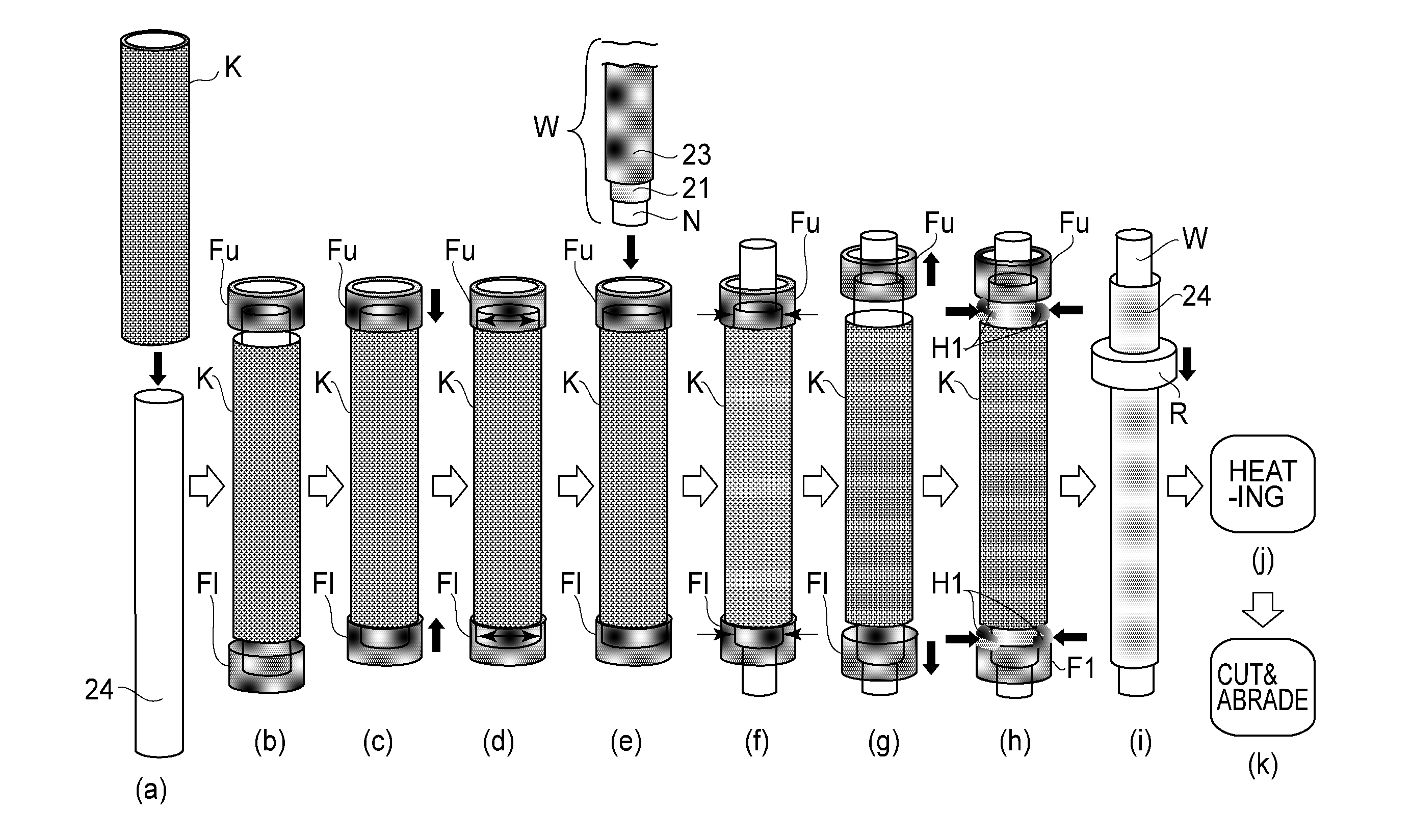
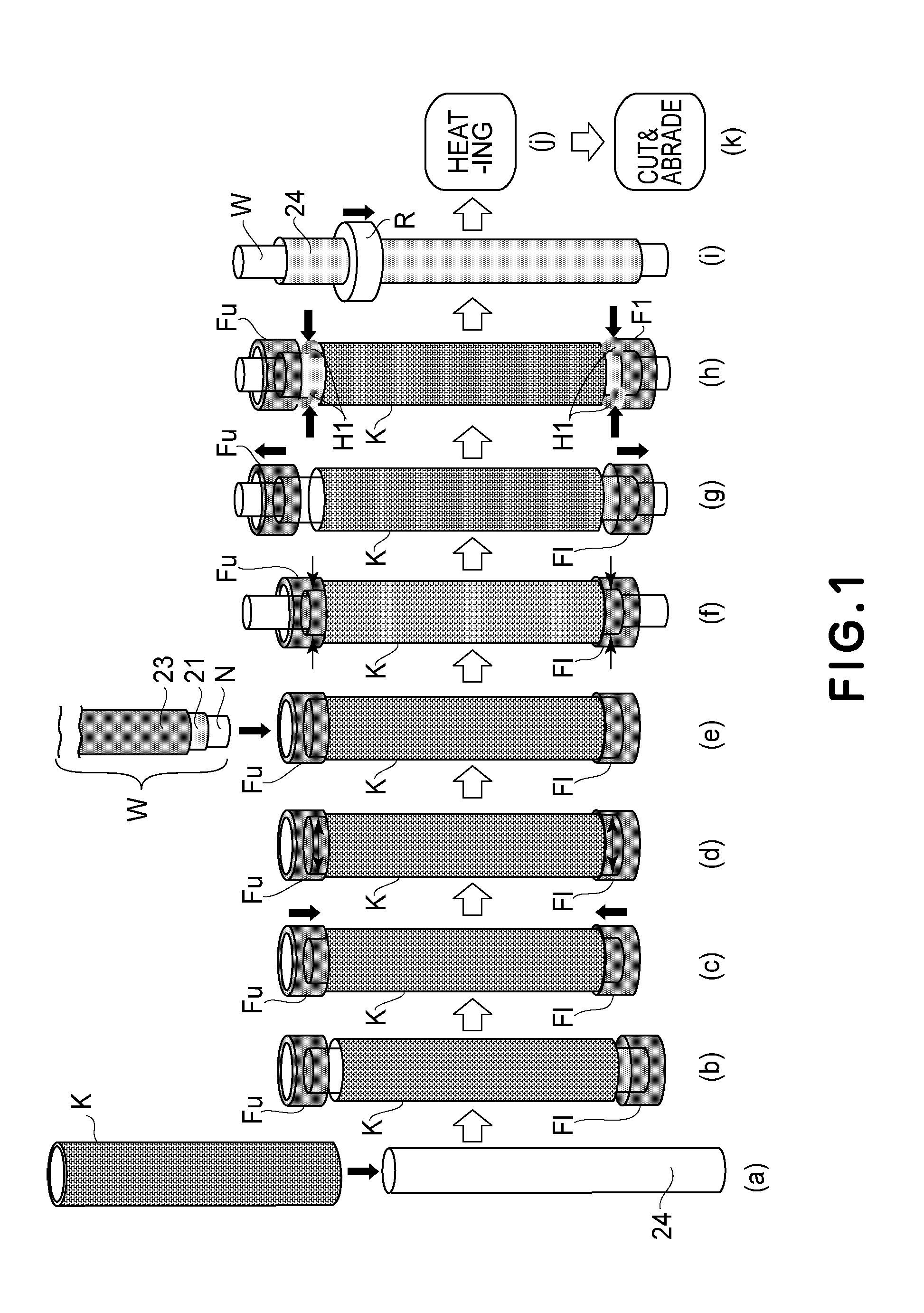
A fixing member manufacturing method includes: a step of holding a longitudinal end of a resin tube by a first holding tool; a step of holding another longitudinal end of the resin tube by a second holding tool; a step of decreasing a distance between the first and second holding tools each holding the resin tube, by a predetermined amount; a step of expanding, after the decreasing step, the resin tube in a radial direction; and a step of externally fitting the resin tube, expanded in the radial direction, around an elastic material coated with an adhesive.

Description

FIELD OF THE INVENTION AND RELATED ART[0001]The present invention relates to a fixing member manufacturing method and a fixing member manufacturing apparatus.[0002]As a fixing member used in a fixing device to be conventionally mounted in an image forming apparatus of an electrophotographic type, a belt-shaped fixing member and a roller-shaped fixing member have been known.[0003]As these fixing members, a fixing member prepared by forming an elastic layer (elastic material) of a heat-resistant rubber or the like on a substrate (base material) and then by providing, on a surface of the elastic layer, a resin layer (such as a fluorine-containing resin layer) having an excellent parting property with respect to a toner has been known.[0004]As such a fixing member, Japanese Laid-Open Patent (JP-A) 2004-276290 discloses that a substrate is inserted into a fluorine-containing resin tube enlarged in diameter and then the fluorine-containing resin tube is fixed by an adhesive with which an ...

Claims


Application Information

Patent Timeline
IPC IPC(8): G03G15/20
CPCG03G15/20G03G15/2017G03G15/2057G03G2215/2032
Inventor AKIYAMA, NAOKISUGIMOTO, HIROTOMIYAHARA, YASUHIROKUME, NOBUYUKIYOSHIDA, YOSHIAKI
Owner CANON KK
Learn More