

Image forming apparatus
a technology of image forming apparatus and forming medium, which is applied in the direction of thin material processing, article separation, transportation and packaging, etc., can solve the problems of troublesome removal of fine pieces, jammed medium, and fine pieces from the image forming apparatus, so as to facilitate the removal of jammed medium and prevent damage to the gears
- Summary
- Abstract
- Description
- Claims
- Application Information
AI Technical Summary
Benefits of technology
Problems solved by technology
Method used
Image


Examples
first embodiment
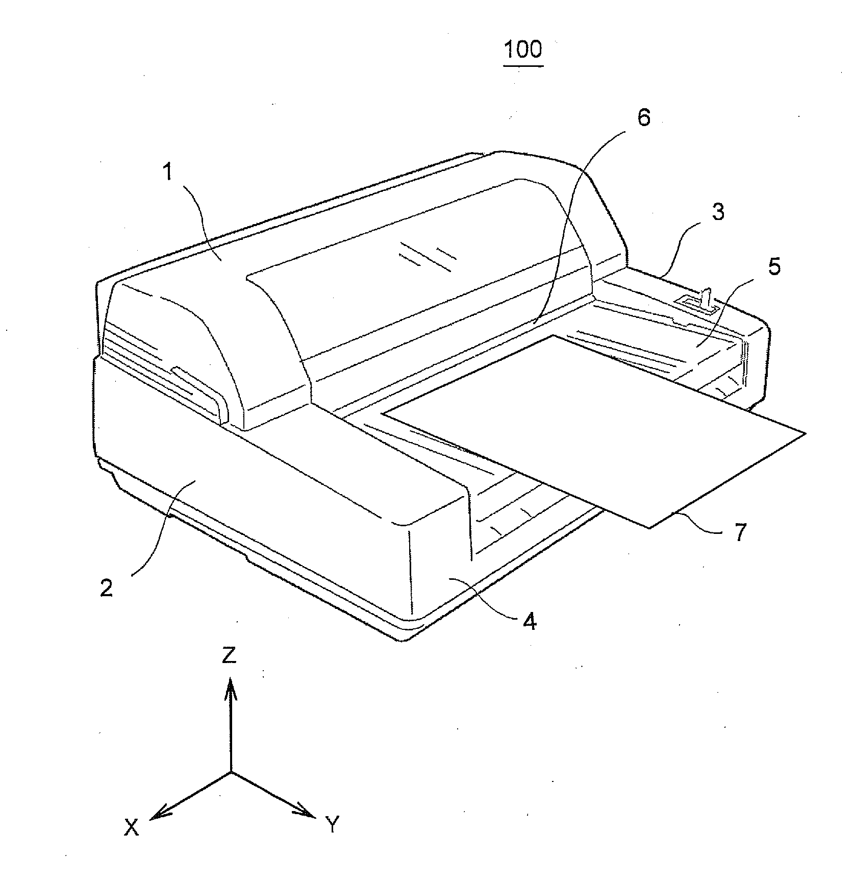
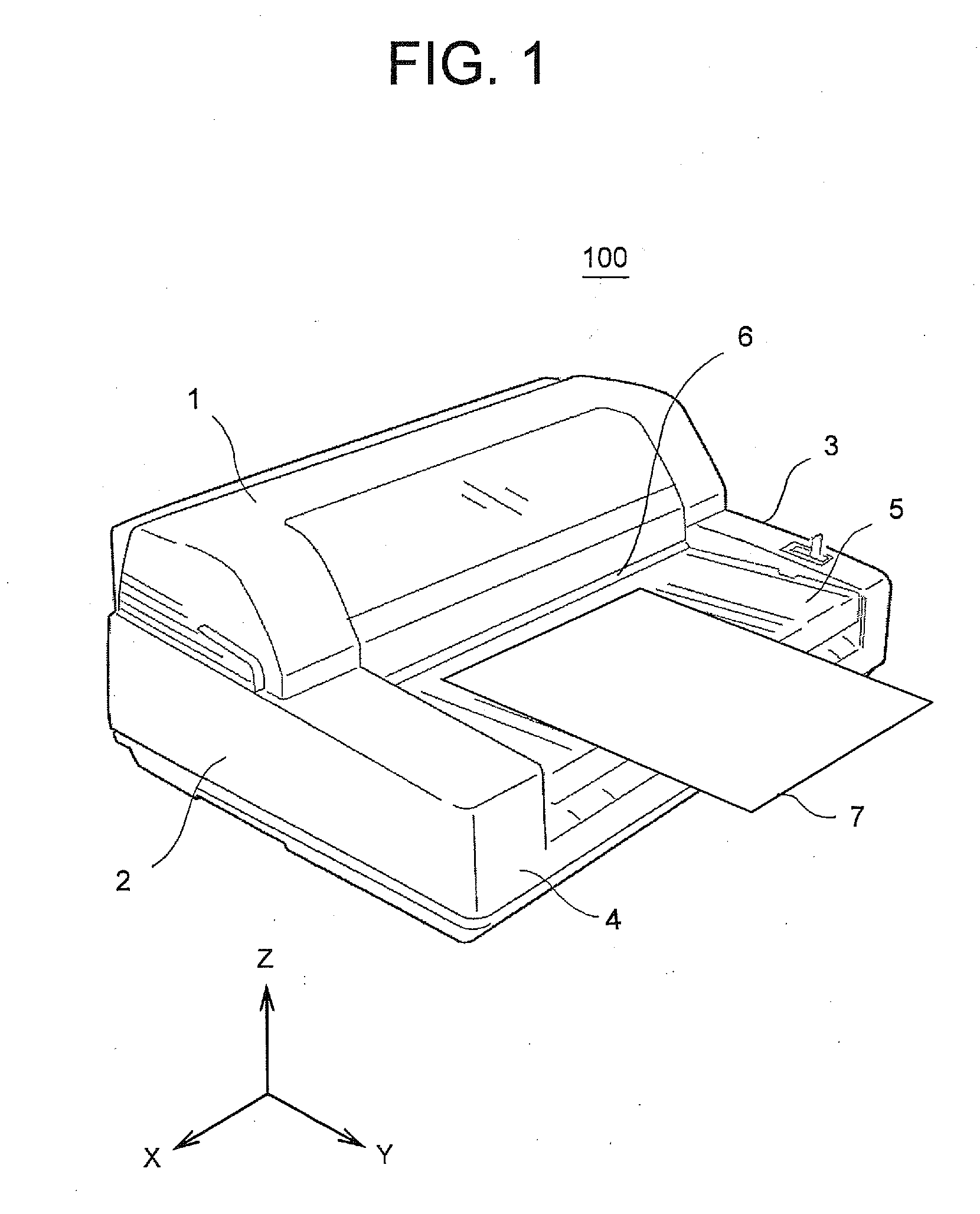
[0039]FIG. 1 is a perspective view showing an external shape of an image forming apparatus according to the first embodiment of the present invention. The image forming apparatus 100 has a main body cover including an upper cover 1, side covers 2 and 3, and a lower cover 4. The image forming apparatus 100 has an elongated shape.
[0040]In FIG. 1, a longitudinal direction of the image forming apparatus 100 is referred to as X direction, a widthwise direction of the image forming apparatus 100 is referred to as Y direction. An XY plane (parallel to the X direction and the Y direction) is a horizontal plane. A direction perpendicular to the XY plane is referred to as Z direction (i.e., a vertical direction). The X, Y and Z directions are provided for convenience of explanation, and do not limit an orientation of the image forming apparatus 100.
[0041]A medium insertion opening 6 is provided on a front surface (i.e., a surface facing +Y direction) of the upper cover 1. The medium insertion...
second embodiment
[0133]Next, the second embodiment of the present invention will be described. In the second embodiment, the cam member 25 and the lock lever 23 described in the first embodiment are integrated. An image forming apparatus of the second embodiment have the same configurations as those of the image forming apparatus of the first embodiment except the integration of the lock lever 23 and the cam member 25.
[0134]FIG. 17 is a perspective view showing a main part of the image forming apparatus of the second embodiment. As shown in FIG. 17, the lock lever 23 described in the first embodiment is not provided on the outer side of the side plate 92 of the upper frame unit 9.
[0135]FIG. 18 is a perspective view showing the image forming apparatus in a state where the upper frame unit 9 is opened. A combined cam member that also serves as a lock lever (referred to as a cam member 75) is provided in the upper frame unit 9. The cam member 75 is configured to function as the cam member 25 and the lo...
PUM
 Abstract
Description
Claims
Application Information