
Color-mapping wand

a color mapping and wand technology, applied in the field of color mapping of the surface, can solve the problems of complex setup of the acquisition of a digital representation of the surface of a three-dimensional,

Inactive Publication Date: 2014-05-01
ZIMET RUBNER YAEL +2
View PDF5 Cites 27 Cited by
  • Summary
  • Abstract
  • Description
  • Claims
  • Application Information

AI Technical Summary

Benefits of technology

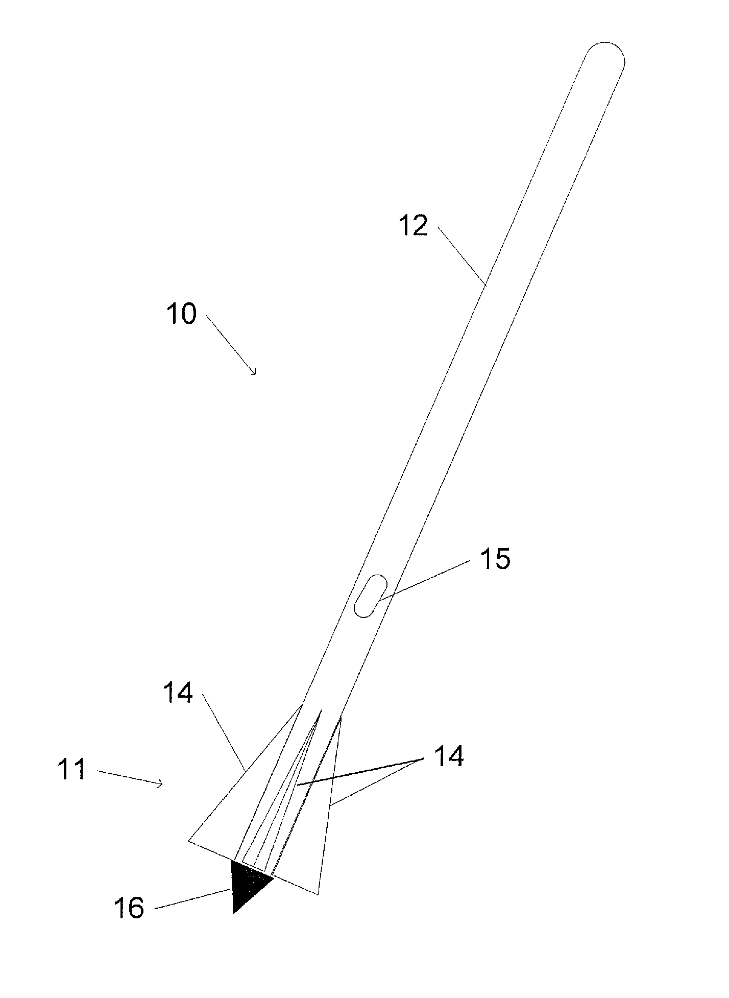
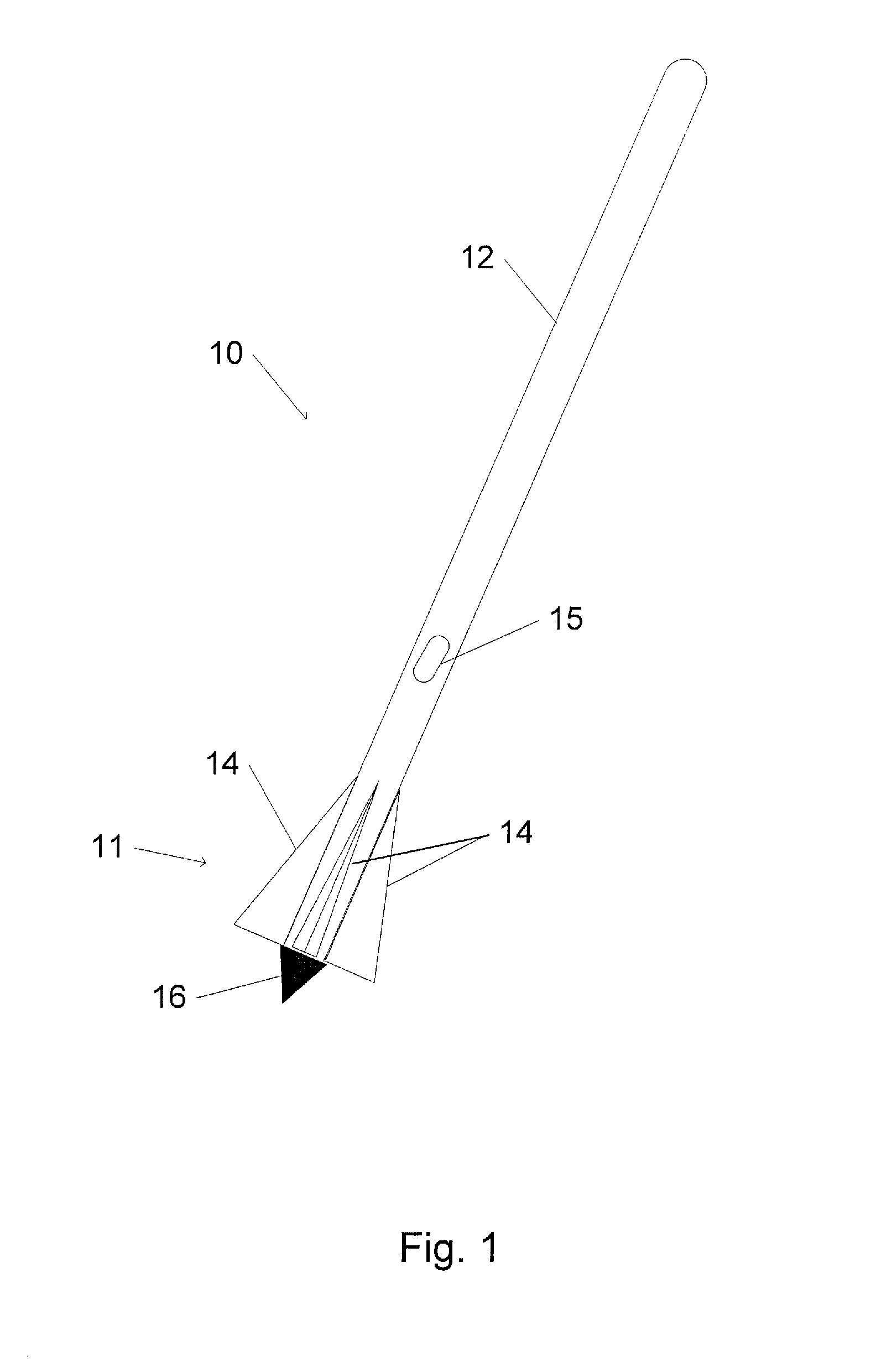
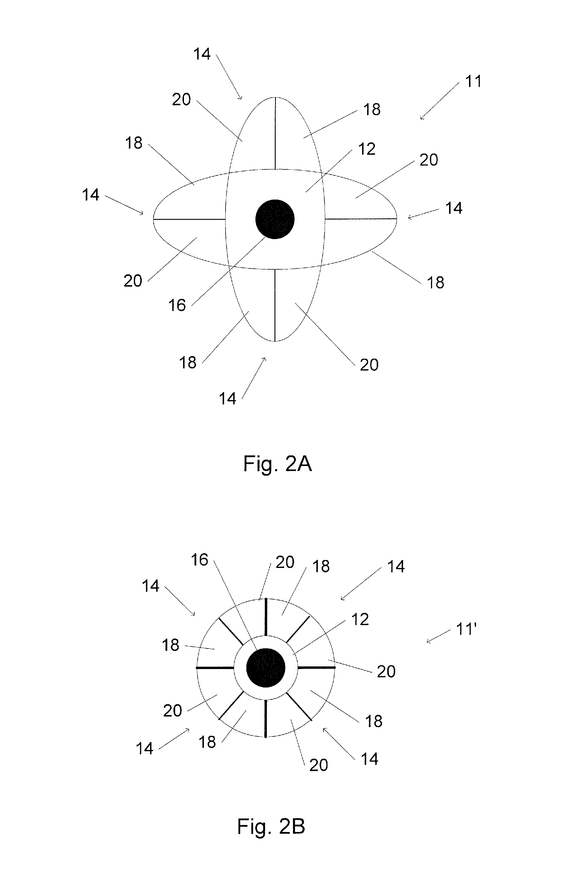
The present invention provides a device with a freely manipulable color-mapping wand that includes a color detector and a navigation sensor. The color detector measures the intensity of light in a spectral range incident from a surface, while the navigation sensor produces a signal that can be used to determine the position of the color-mapping wand. The device also includes a plurality of fiducial markers that can be detected by the navigation sensor to help with positioning. The color detector can measure the intensity of light in different regions of the surface, and the navigation sensor can include a linear accelerometer, rotation rate sensor, gyroscope, compass, inertial measurement unit, pressure sensor, display device, audio output device, imaging device, or user-operable control. The color-mapping method involves measuring the intensity of light in a spectral range incident from a surface, calculating the color of the region based on the measured intensity, and incorporating the calculated color into a representation of the colored surface. The device can also calibrate the color detector and operate it concurrently with the navigation sensor. The technical effects of the invention include improved accuracy and efficiency in color mapping and navigation.

Problems solved by technology

However, acquisition of a digital representation of a surface of a three-dimensional often involves complex setups.

Method used


Image

  • Color-mapping wand
  • Color-mapping wand
  • Color-mapping wand

Examples


Embodiment Construction

[0037]In the following detailed description, numerous specific details are set forth in order to provide a thorough understanding of the invention. However, it will be understood by those of ordinary skill in the art that the invention may be practiced without these specific details. In other instances, well-known methods, procedures, components, modules, units and / or circuits have not been described in detail so as not to obscure the invention.

[0038]In accordance with embodiments of the present invention, a color-mapping wand is capable of forming a digital representation of parts of a surface, such as a surface of a three-dimensional object. The color-mapping wand includes one or more color sensors for measuring the color of the surface. The color-mapping wand includes one or more navigation sensors for enabling a processor that is associated with the color-mapping wand to determine a position of the wand relative to the surface (or to another coordinate system or reference point)...


PUM


Abstract

A device includes a freely manipulable color-mapping wand. The wand includes at least one color detector for measuring an intensity of light within at least one spectral range that is incident from a region of a surface. A navigation sensor produces a signal that is interpretable to yield a position of at least a portion of the color-mapping wand.

Description

FIELD OF THE INVENTION[0001]The present invention relates to color mapping of a surface. More particularly, the present invention relates to a color-mapping wand and a method for color mapping of a surface using the wand.BACKGROUND OF THE INVENTION[0002]It is often convenient to acquire a digital representation of a surface or object. Such digital representations may be stored on a digital data storage medium for later recall, reference, or manipulation. A digital representation may be stored or archived in a compact form, may be sent electronically from one computer to another, may be rendered for display on a computer screen or monitor, or may be otherwise digitally manipulated by a suitable computer application.[0003]For example, a displayable digital representation of a surface or object may be rotated so as to display different views of the object. Other factors that affect the appearance of a surface or object may also be manipulated, such as illumination and surface coloring....

Claims


Application Information

Patent Timeline
IPC IPC(8): G06K9/20
CPCG06F3/03G01J3/00G06F3/0304G01J3/0289G01J3/50
Inventor ZIMET-RUBNER, YAELLIVNE, ALINARUBNER, AVRAHAM YAIR
Owner ZIMET RUBNER YAEL
Learn More