Eureka AIR delivers breakthrough ideas for toughest innovation challenges, trusted by R&D personnel around the world.

Color mapping techniques for color imaging devices

a color imaging and color mapping technology, applied in the field of color mapping techniques for color imaging devices, can solve the problems of not using the full capabilities of the target device, the target's expanded color range is wasted, and the recorded colors of the input signal may not be reproducible within the target color gamut, so as to improve calorimetric accuracy, smooth out transitions, and preserve memory colors effectively

Active Publication Date: 2008-02-21
TEXAS INSTR INC
View PDF6 Cites 37 Cited by
  • Summary
  • Abstract
  • Description
  • Claims
  • Application Information

AI Technical Summary

Benefits of technology

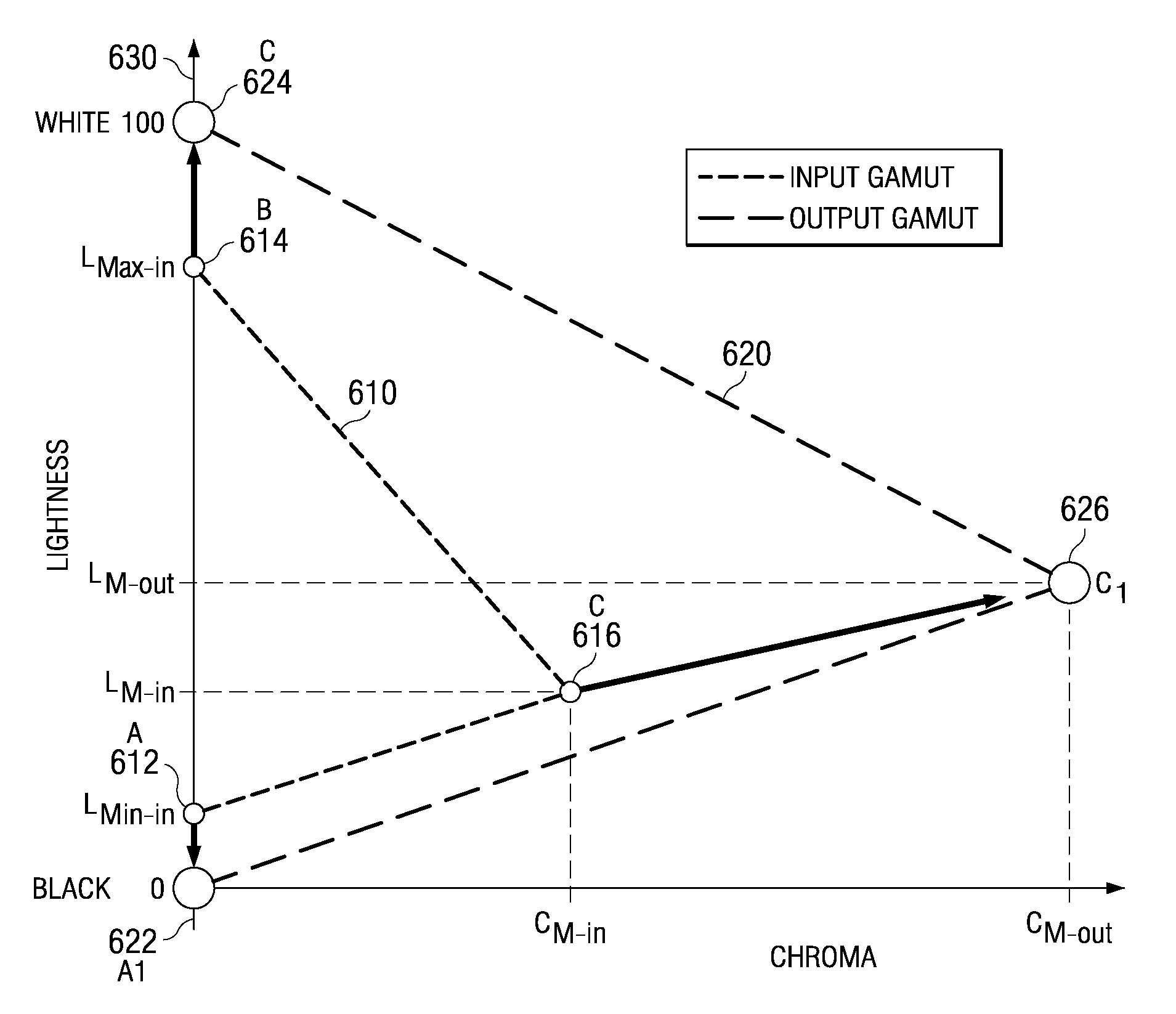
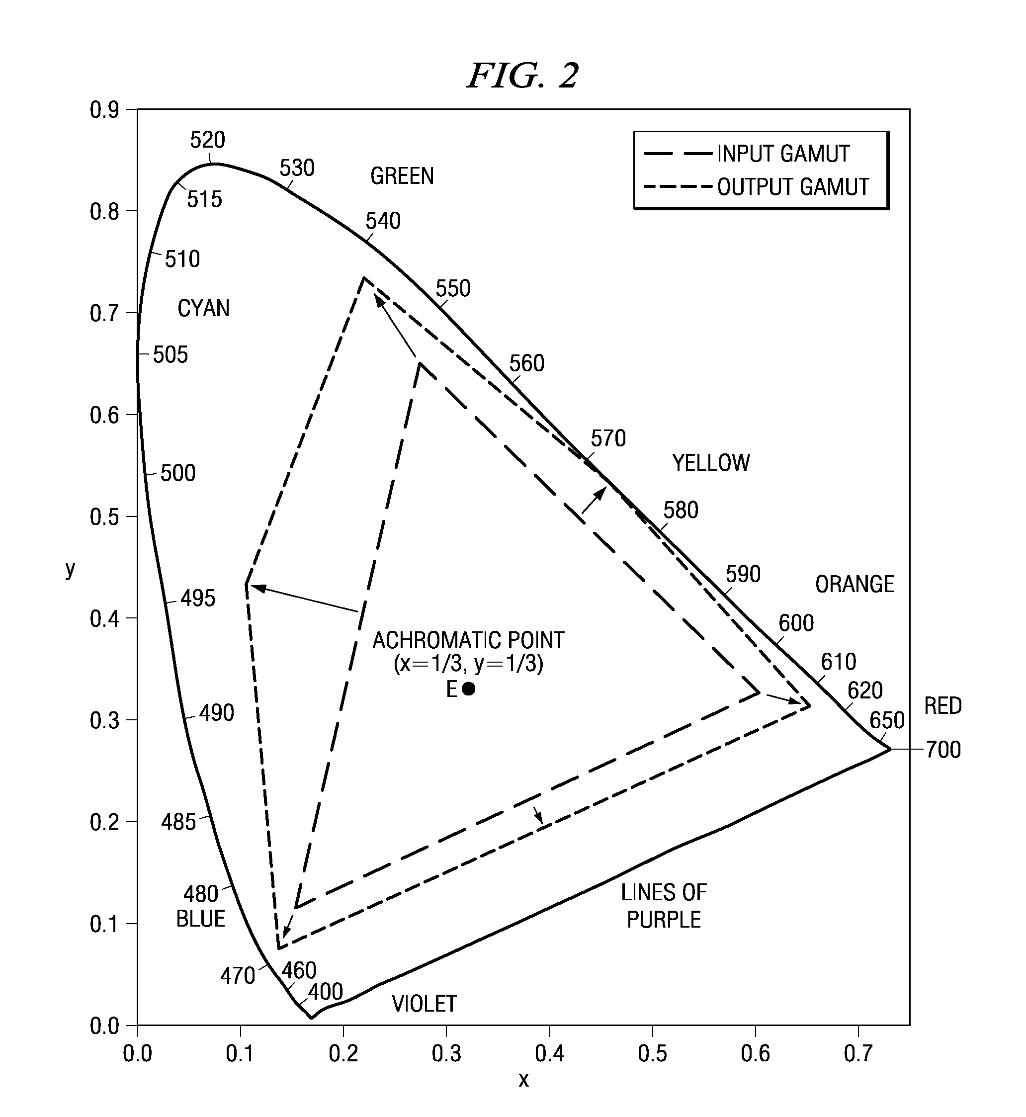
[0009]Disclosed embodiments may utilize rubber-sheet polynomial mapping to map color points from the input color gamut to the output color gamut. By employing polynomial mapping (rather than conventional linear mapping), additional terms may be introduced, providing additional control points that allow for generation of a better fit. The higher order terms allow for better mapping, producing a better fit since additional information (besides the extreme points of the color gamut) may be factored into the mapping. In particular, such polynomial mapping provides a better fit when one or more of the color gamuts is irregularly shaped (such as having concavity), or when it is desirable to preserve certain colors (such as the achromatic colors).
[0011]Disclosed embodiments may also make use of a memory color look-up table. Such a technique would faithfully reproduce any memory colors that are located within both the color gamuts, so that there would be no unintended distortion of these important memory colors during the color mapping process. Typically, disclosed embodiments use a weighting system based on the probability that a particular color in the input color gamut is a memory color, in order to smooth out transitions while preserving memory colors effectively.
[0012]Embodiments may utilize either polynomial rubber-sheet mapping or a memory color look-up table independently to improve the calorimetric accuracy when mapping from one color gamut to another color gamut, or they may use both of these techniques together. By using a memory color look-up table in conjunction with polynomial mapping, accurate image reproduction may be possible without the need for too many additional terms. Thus, a memory color look-up table may operate to simplify the polynomial used for the rubber-sheet mapping technique while providing for accurate mapping.

Problems solved by technology

As a result, some of the recorded colors from the input signal may not be reproducible within the target color gamut.
In such an instance, the target device could simply reproduce the images associated with the input signal precisely as the source might, but this would mean that the target device would not be using its full capabilities; much of the target's expanded color range would be wasted.
If on the other hand, the input signal from the source device has a larger color gamut than does the target device, then the target display device would be incapable of recreating the visual image precisely in accordance with the input signal of the source device.
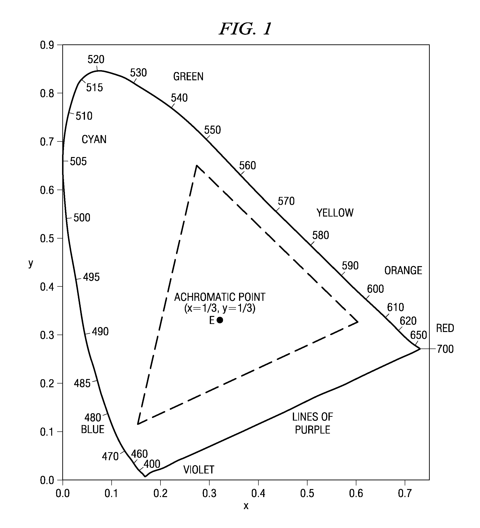
Mapping from one color gamut to another within the x-y chromaticity space is limited by its very nature to a linear or piecewise-linear projection due to the linearity of the XYZ color space.
Linear or piecewise-linear mapping between color gamuts may be restrictive, preventing effective color mapping that achieves calorimetric accuracy.
While this type of linear color mapping may be adequate if color gamuts within the x-y chromaticity space are sufficiently similar, linear mapping is often not particularly effective, possibly distorting colors so that the image colors are not reproduced particularly faithfully.
The goal is to preserve calorimetric accuracy, and linear mapping may not be able to achieve this result given its constraints.
In addition, such a conventional linear mapping system may not effectively preserve memory colors.
Any distortion of a memory color perceived by a viewer tends to drastically reduce the believability of the reproduced image.
Whenever a display device does not accurately reproduce such memory colors, the image tends to be viewed as unrealistic.
Conventional color mapping systems may not effectively maintain or reproduce such memory colors, resulting in a less effective image.

Method used


Image

  • Color mapping techniques for color imaging devices
  • Color mapping techniques for color imaging devices
  • Color mapping techniques for color imaging devices

Examples


Embodiment Construction

[0027]The disclosed embodiments generally employ a three dimensional perceptual color space to model color gamuts. Examples of such perceptual color spaces would be CIELUV and CIELAB, which represent colors in a more uniform manner. Perceptual color spaces represent color gamuts using three distinct axes: hue, lightness, and chroma. Thus, any color gamut in a perceptual color space may be represented graphically as a 3-D raised relief map, showing the relationship between hue, lightness, and chroma. By way of example, FIG. 3 illustrates an exemplary input color gamut 300 as a raised relief map, while FIG. 4 illustrates an exemplary output color gamut 400 as a raised relief map. As has been discussed above, the input 300 and output 400 color gamuts often differ, as may be seen by comparing the raised relief maps of the input 300 and output 400 color gamuts shown in FIG. 3 and FIG. 4.

[0028]It is often desirable to maintain hue when mapping an input color gamut to a different output co...


PUM


Abstract

Disclosed embodiments relate to techniques for color gamut mapping when an input signal transmitting color visual images has a different color gamut than does the output display device. Polynomial rubber-sheet mapping may be used to translate the input color gamut to the output color gamut on a hue-by-hue basis within a three-dimensional perceptual color space. Also, a memory color look-up table may be used to preserve memory colors in the input gamut which are capable of reproduction within the output gamut. By using such techniques alone or in combination, it may be possible to more effectively map an input color gamut to a different output color gamut with improved calorimetric accuracy.

Description

FIELD OF THE INVENTION[0001]The disclosed embodiments relate generally to techniques for color mapping one color gamut to another color gamut, specifically the type of mapping typically used when the color gamut of a visual display device does not match the color gamut of an input signal with information regarding a visual image to be reproduced.BACKGROUND OF THE INVENTION[0002]“Color gamut” is a term used to describe the range of colors available in a particular system. Different types of display systems tend to each have their own specific color gamut, depending upon their technological limits. Oftentimes, in visual display systems (such as digital micromirror devices, plasma displays, or LCDs, used as video displays, computer screens, or projectors, for example) the input or source color gamut differs from the output or display color gamut. This may be the case if, for example, the input signal was recorded based on a standard Rec. 709-based monitor (source device), while the act...

Claims


Application Information

Patent Timeline
IPC IPC(8): G06F15/00
CPCG06T11/001H04N1/6058G09G2340/06G09G5/06
Inventor RAMANATH, RAJEEVPETTITT, GREGORY S.
Owner TEXAS INSTR INC
Why Eureka
Eureka Blog
Learn More