Determining color mappings for a color printer

a color printer and color mapping technology, applied in the field of color printing, can solve the problems of tedious and time-consuming to derive a new printer look-up table, post-factory compensation based on effects, etc., and achieve the effects of high color fidelity, fast binary search, and relative ease of operation

Inactive Publication Date: 2005-03-22
CANON KK
View PDF13 Cites 38 Cited by
  • Summary
  • Abstract
  • Description
  • Claims
  • Application Information

AI Technical Summary

Benefits of technology

Preferably, interpolation according to the invention is tetrahedral so as to minimize color discontinuities and color gradient effects between adjacent cells of the forward model look-up table.
Because the invention performs a binary search only for the purpose of locating the cell that contains the device independent target color, the binary search is quick and can be performed with relative ease. For example, in a situation where the forward model look-up table is a 9×9×9 uniform grid in CMY device dependent colors, the binary search can locate the cell for a device independent target color within about three and at most four iterations of the binary search. Moreover, since interpolation is performed using the grid points for the cell so located, high color fidelity for the reverse model look-up table is obtained with good continuity and color gradient smoothness.

Problems solved by technology

One difficulty with this approach is the determination of entries for the look-up table that gives the transformation from device independent colors to device dependent colors for the printer.
A single derivation of a look-up table, however, does not allow for post-factory compensation based on effects such as printer aging, selection of different inks with different spectral characteristics, selection of different print media, and other effects which change printout characteristics.
Although it is possible to recalibrate the printer by printout of new color patches and by empirical measurement of the resulting device independent colors, it is still difficult, tedious and time consuming to derive a new printer look-up table, even though such derivation is ordinarily performed by a computer.

Method used


Image

  • Determining color mappings for a color printer
  • Determining color mappings for a color printer
  • Determining color mappings for a color printer

Examples


Embodiment Construction

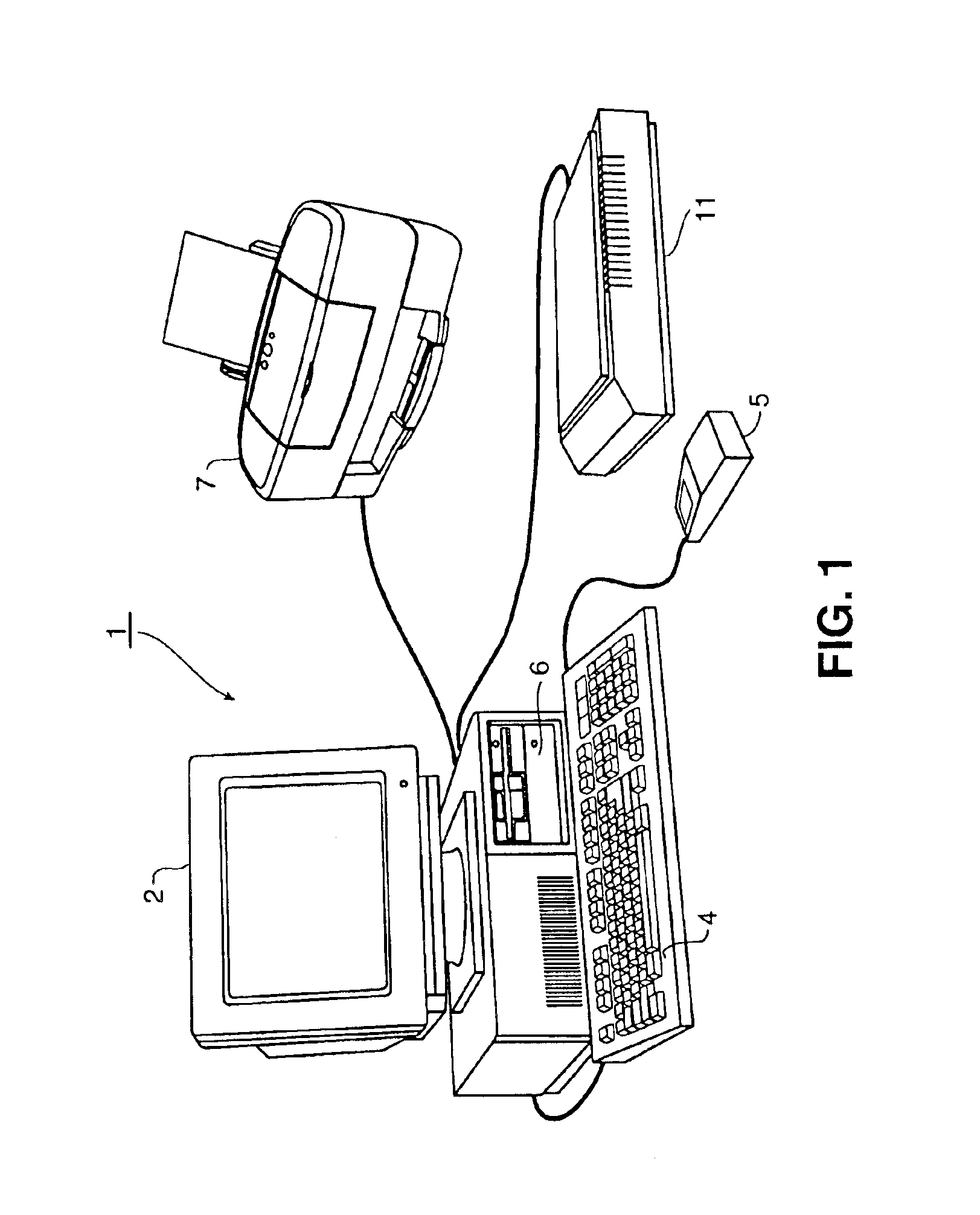
FIG. 1 is a representational view of a computer system in which the present invention may be utilized. Computer system 1 may be a Macintosh, PC-compatible, or other type of computer having an operating system such as Microsoft® Windows®. Provided with computer system 1 are display 2 which may be a color monitor, keyboard 4 for entering user commands, and pointing device 5, such as a mouse, for pointing to and for manipulating graphical user interfaces and other objects displayed on display 2.

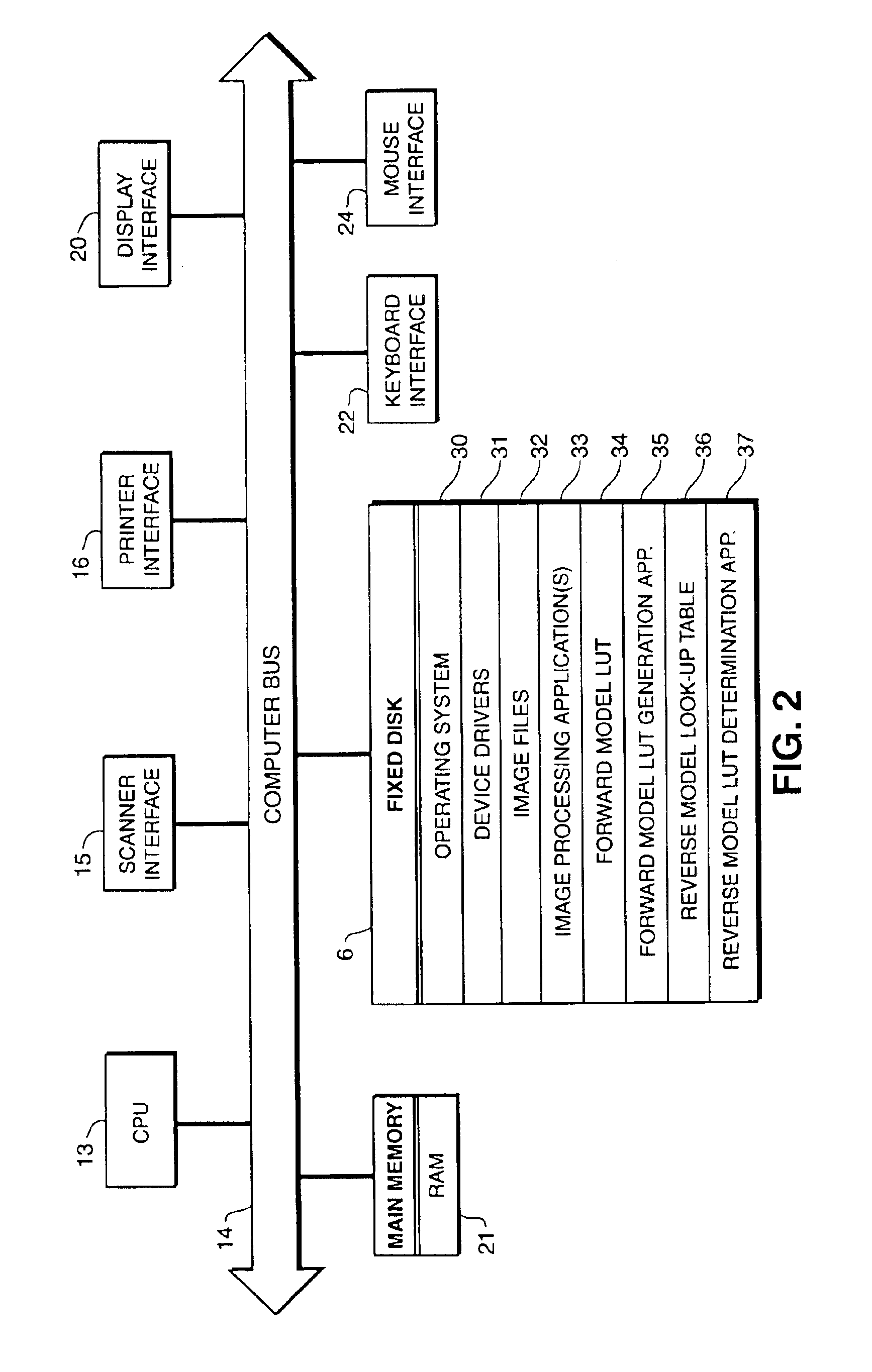
Computer system 1 also includes a mass storage device such as fixed disk 6 for storing computer-executable process steps for image processing applications, process steps for generating a forward model look-up table, process steps for determining a reverse model look-up table according to the invention, and other application programs and data. Such storage may also be provided by other storage media such as CD-ROM (not shown).

Printer 7 is provided for outputting images such as images from image p...


PUM


Abstract

A method for deriving a reverse model look-up table whose entries represent device dependent colors as a function of device independent colors, based on a forward model look-up table whose entries represent device independent colors obtained in response to printout of corresponding device dependent colors. For each device independent target color, a binary search of the forward model look-up table is performed so as to locate a cell that contains the device independent target color. The grid points from the forward model look-up table that define the cell are interpolated so as to obtain device dependent colors corresponding to the device independent target color. The device dependent color is stored at the grid point for the reverse model look-up table at a position corresponding to the device independent target color.

Description

BACKGROUND OF THE INVENTION1. Field of the InventionThe present invention relates to color printing, and in particular relates to a fast, iterative method for deriving a look-up table that represents the color mapping for a printer from device independent colors (such as a color in CIEXYZ or CIELAB color space) to a color in a device dependent color space (such as a color in CMY or CMYK color space).2. Background of the InventionIn conventional computer systems that print color images on a color printer, the precise colors actually printed by the printer are calculated by the computer using a look-up table. Specifically, the look-up table is arranged as a three-dimensional grid of cells, with each entry in the grid representing printer colorant values (such as cyan, magenta, yellow and black colorant values) as a function of some desired color in a different (usually device independent) color space. Based on a desired color, the computer accesses the look-up table to determine the p...

Claims


Application Information

Patent Timeline
Patent Type & Authority Patents(United States)
IPC IPC(8): H04N1/60
CPCH04N1/6033H04N1/6019
Inventor KULKARNI, MANISH
Owner CANON KK
Why Eureka
Try Eureka