Programmable implants and methods of using programmable implants to repair bone structures

a technology of implantable implants and bone structures, applied in the field of implants, can solve the problems of reducing the size of the bone column fusing the superior and inferior vertebral bodies, increasing pressure, and affecting bone growth

Active Publication Date: 2014-05-01
4-WEB
View PDF3 Cites 122 Cited by
  • Summary
  • Abstract
  • Description
  • Claims
  • Application Information

AI Technical Summary

Problems solved by technology

For example, large rims may impede bone growth and reduce the size of the bone column fusing the superior and inferior vertebral bodies.
This may increase the pressure on smaller areas of the vertebral endplates and may potentially lead to stress risers in the vertebral endplates.
Further, while bone graft material is often used in conjunction with implants to encourage bone growth, the open column design of implants may reduce the likelihood of bone graft material from securing itself to the implant which could result in a bio-mechanical cooperation that is not conducive to promoting good fusion.
High-pressure states, however, may be difficult to create and maintain for the bone graft material in an implant.
In particular, the lack of attachment of the bulk graft cannot fully accept or integrate the differential loading anticipated in normal kinetic scope.

Method used


Image

  • Programmable implants and methods of using programmable implants to repair bone structures
  • Programmable implants and methods of using programmable implants to repair bone structures
  • Programmable implants and methods of using programmable implants to repair bone structures

Examples


Embodiment Construction

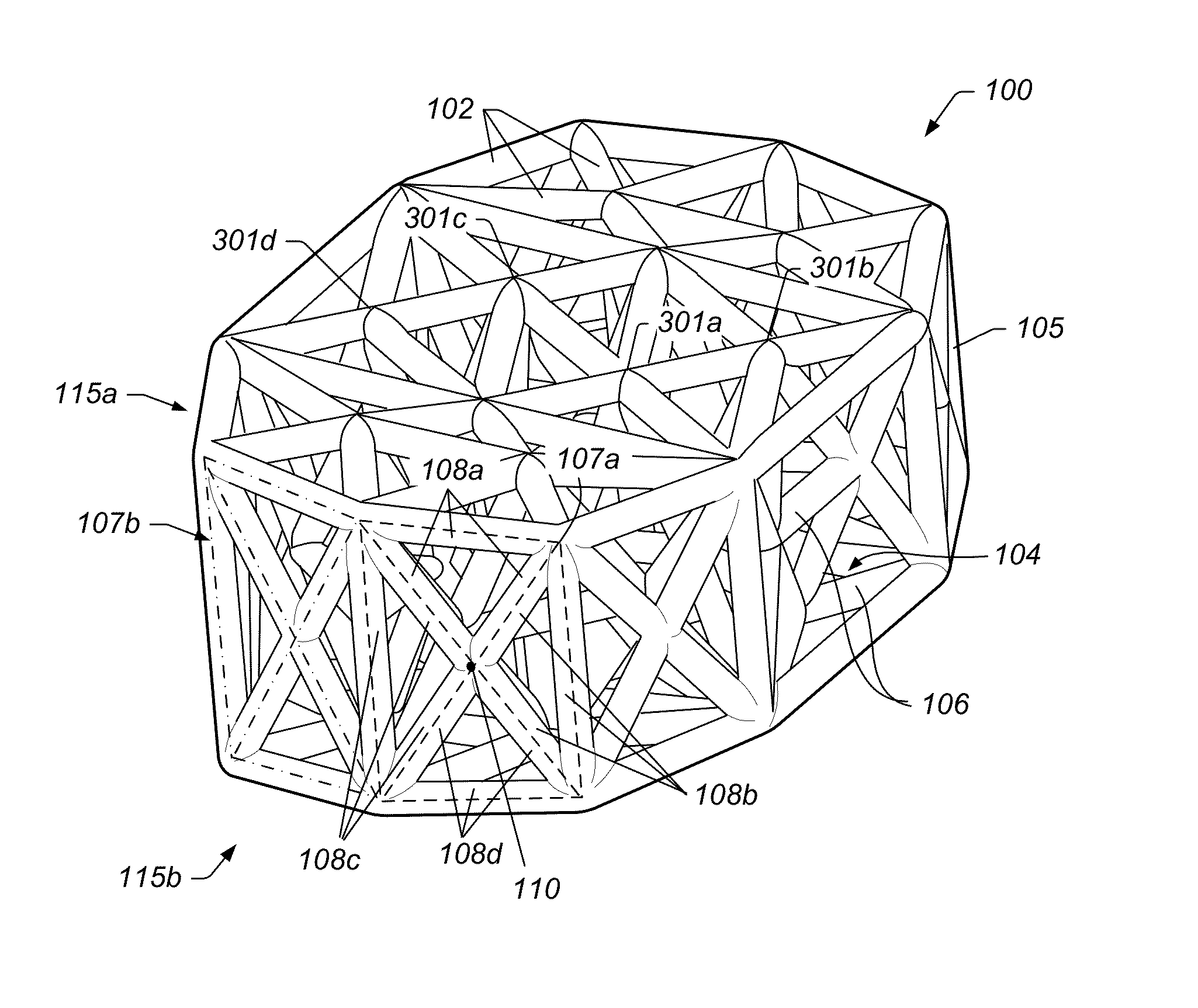
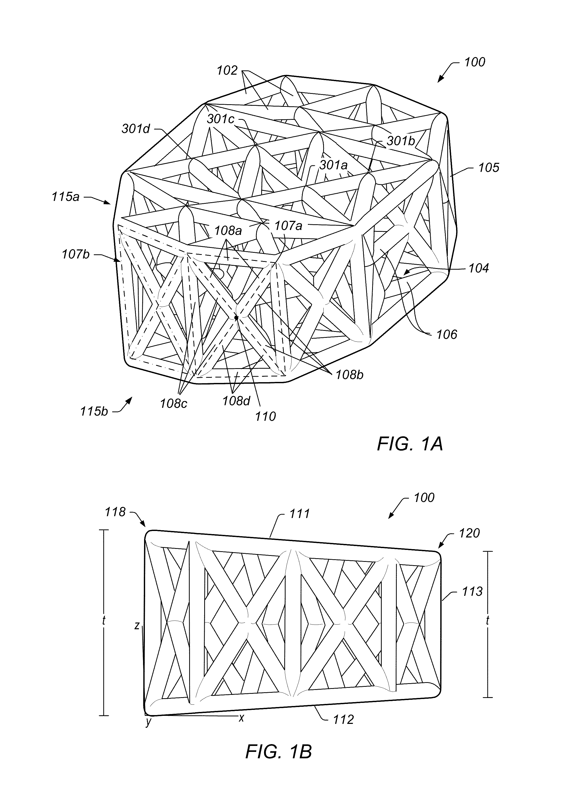
[0025]FIGS. 1A-1B illustrate views of implant 100, according to an embodiment. The specifically depicted implant 100 may be used, for example, in anterior lumbar inter-body fusion (ALIF) or posterior lumbar inter-body fusion (PLIF), however, it should be understood that implant 100 nay have a variety of shapes suitable for bone fusion applications. In some embodiments, implant 100 may include a web structure with one or more trusses 102 (e.g., planar and space trusses). Implant 100 may be used in various types of implants for humans or animals such as spinal implants, corpectomy devices, knee replacements, hip replacements, long bone reconstruction scaffolding, and cranio-maxifacial implants foot and ankle, hand and wrist, shoulder and elbow (large joint, small joint, extremity as well as custom trauma implants). Other implant uses are also contemplated.

[0026]As used herein a “truss structure” is a structure having one or more elongate struts connected at joints referred to as nodes...


PUM

PropertyMeasurementUnit
diameteraaaaaaaaaa
lengthaaaaaaaaaa
diameteraaaaaaaaaa

Abstract

Various embodiments of implant systems and related apparatus, and methods of operating the same are described herein. In various embodiments, an implant for interfacing with a bone structure includes a web structure, including a space truss, configured to interface with human bone tissue. The space truss includes two or more planar truss units having a plurality of struts joined at nodes. Implants are optimized for the expected stress applied at the bone structure site.

Description

PRIORITY CLAIM[0001]This application claims the benefit of U.S. Provisional Application No. 61 / 705,403 filed on Sep. 25, 2012 and U.S. Provisional Application No. 61 / 801,597 filed on Mar. 15, 2013.BACKGROUND OF THE INVENTION[0002]1. Field of the Invention[0003]The present invention relates generally to medical devices and, more specifically, to implants.[0004]2. Description of the Relevant Art[0005]Implants may be used in human and / or animals to support and / or secure one or more bones. For example, implants may be used in the spine to support and / or replace damaged tissue between the vertebrae in the spine. Once implanted between two vertebrae, the implant may provide support between the two vertebrae and bone growth may take place around and through the implant to at least partially fuse the two vertebrae for long-term support. Implants may include relatively large rims with solid material that may cover, for example, 50% of the area that interacts with the endplate. The rim may pr...

Claims


Application Information

Patent Timeline
Patent Type & Authority Applications(United States)
IPC IPC(8): A61F2/44
CPCA61F2/4455A61F2002/30143A61F2002/30156A61F2002/30906A61F2002/30909A61F2002/3092A61F2002/3093A61F2002/30952A61F2002/30968A61F2002/3097A61F2002/30985A61F2310/00017A61F2310/00023A61F2310/00029A61F2310/00179A61F2310/00796A61F2/2803A61F2/30907A61F2/447A61F2/4611A61F2002/2835A61F2002/30153A61F2002/30158A61F2002/30179A61F2002/30273A61F2002/30275A61F2002/30281A61F2002/30599A61F2002/30841A61F2002/30914A61F2002/30943A61F2002/30953A61F2002/30957A61F2002/30962A61F2310/00047A61F2310/00598A61F2310/00958A61F2310/0097A61F2310/00976A61F2/30A61F2002/30593A61F2002/3028A61F2/28A61F2/30942A61F2/32A61F2/38A61F2/4202A61F2/4225A61F2/44A61F2/4465A61F2002/3014A61F2002/30891
Inventor HUNT, JESSEE
Owner 4-WEB
Why Eureka
Try Eureka