Electrical cable seal and method of making

a technology of electrical cables and sealing cables, applied in the field of sealing cables, can solve the problems of limiting the accumulation of uncombusted fuel, and unsatisfactory fuel to continu

Active Publication Date: 2014-05-08
BAKER HUGHES INC
View PDF0 Cites 24 Cited by
  • Summary
  • Abstract
  • Description
  • Claims
  • Application Information

AI Technical Summary

Benefits of technology

[0007]One aspect of the invention provides a cable assembly including a housing. The housing defines an internal volume and the housing includes a first cable end portion and a second cable end portion. The cable assembly also includes at least two cable fittings, wherein the first cable end portion and the second cable end portion are connected to a cable fitting through a first seal. Each of the cable fittings define a cable fitting opening. The cable assembly further includes an electrical cable. The electrical cable is inserted through the cable fitting opening in each cable fitting and through the internal volume of the housing. The cable assembly still further includes a second seal located in the annular spaces between the electrical cable and each cable fitting opening. The second seal is configured to prevent moisture and contaminants from passing through the cable fitting opening.
[0009]Another aspect of the invention provides a method of sealing an electrical cable and a flexible conduit including the step of providing a housing. The housing defines an internal volume and the housing includes a first cable end portion and a second cable end portion. The method also includes the step of connecting a cable fitting to each of the first cable end portion and the second cable end portion using a first seal. Each of the cable fittings defines a cable fitting opening. The method further includes the step of providing an electrical cable, wherein the electrical cable is inserted through the cable fitting opening in each cable fitting and through the internal volume of the housing. The method still further includes the step of sealing the annular spaces between the electrical cable and each cable fitting opening with a second seal, the second seal preventing moisture and contaminants from passing through the cable fitting opening.

Problems solved by technology

If the flame becomes extinguished, commonly referred to as a flame-out condition, it is undesirable for fuel to continue to be fed into the hot combustion chamber without appropriate ignition.
Consequently, if the ignition flame is extinguished within the combustion chamber, the fuel feed into the combustion chamber should be quickly terminated and thus limit un-combusted fuel build up.

Method used


Image

  • Electrical cable seal and method of making
  • Electrical cable seal and method of making
  • Electrical cable seal and method of making

Examples


Embodiment Construction

[0017]Example embodiments that incorporate one or more aspects of the invention are described and illustrated in the drawings. These illustrated examples are not intended to be a limitation on the invention. For example, one or more aspects of the invention can be utilized in other embodiments and even other types of devices. Moreover, certain terminology is used herein for convenience only and is not to be taken as a limitation on the invention. Still further, in the drawings, the same reference numerals are employed for designating the same elements.

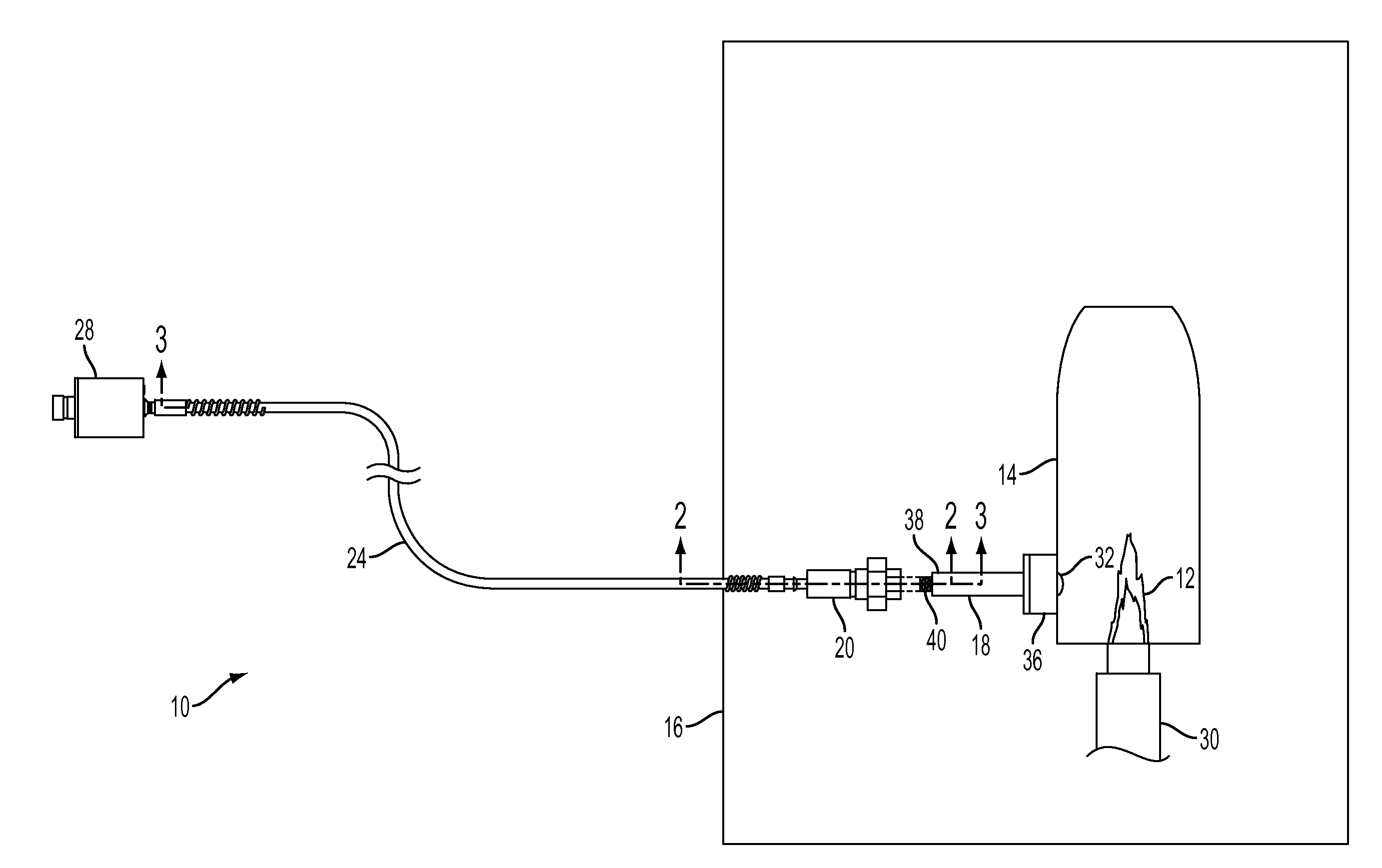
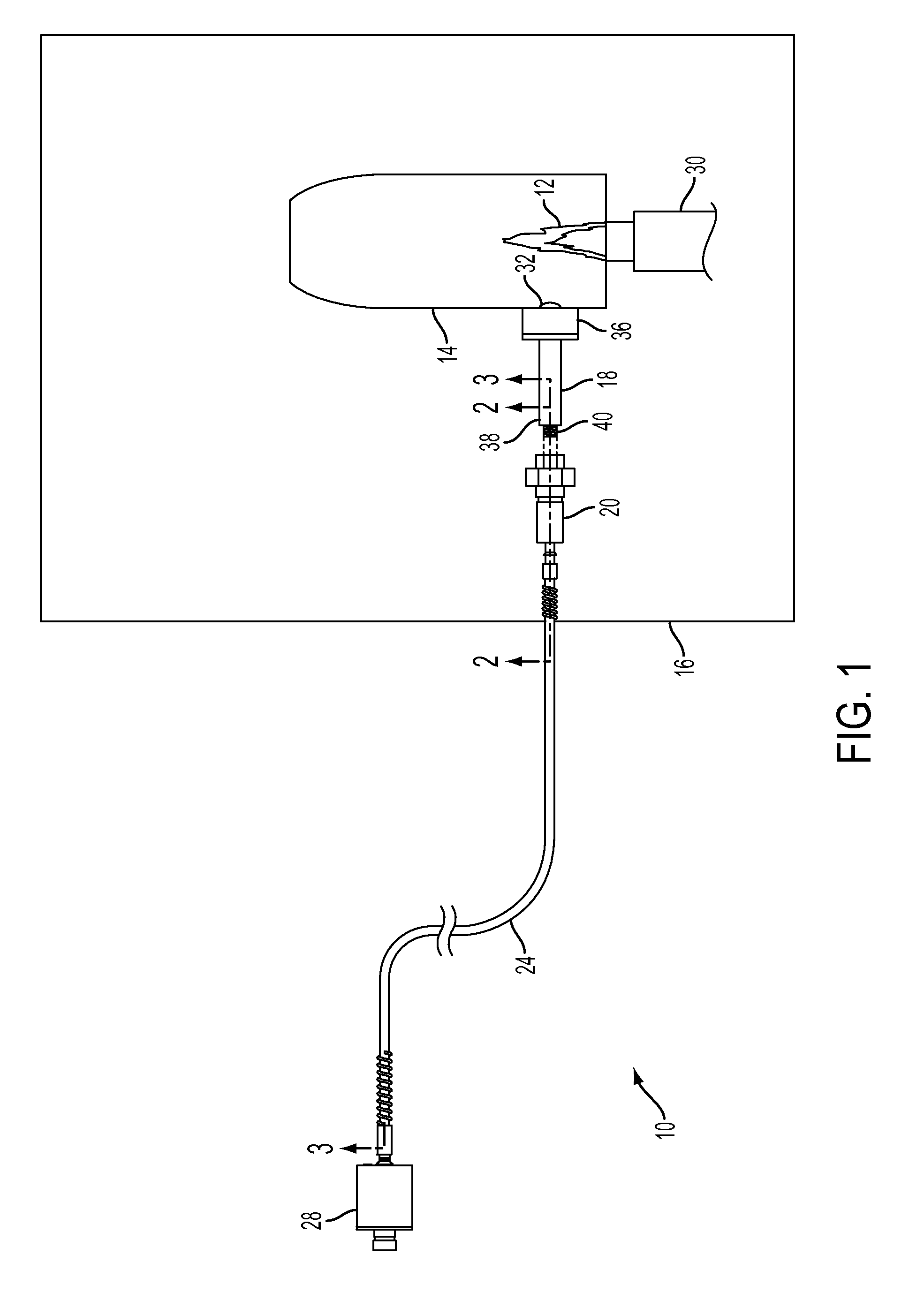
[0018]FIG. 1 schematically illustrates an example flame sensor apparatus 10 for monitoring specific characteristics of a flame 12. The flame 12 is located within a combustion chamber 14 of a turbine 16 and emits electromagnetic radiation energy. A sight tube 18 can be attached to the combustion chamber 14. A sensor assembly 20 is operably connected with the combustion chamber 14 and can receive the electromagnetic radiation energy from...


PUM

PropertyMeasurementUnit
temperatureaaaaaaaaaa
temperaturesaaaaaaaaaa

Abstract

A flame sensor apparatus and a cable assembly apparatus are provided for use in sensing characteristics of a flame within a combustion chamber. The flame sensor apparatus includes an electrical assembly remote from a sensor assembly. A cable assembly extends between the sensor assembly and the electrical assembly. The cable assembly includes two cable ends and a housing that defines an internal volume. Cable fittings are connected to the cable ends through a first seal. An electrical cable is inserted through cable fitting openings in each cable fitting and the internal volume of the housing. A second seal is located in the annular spaces between the electrical cable and each cable fitting opening, configured to prevent moisture and contaminants from passing through the cable fitting opening. Additionally, a method of sealing an electrical cable and a flexible conduit is provided.

Description

BACKGROUND OF THE INVENTION[0001]1. Field of the Invention[0002]The invention relates to a flame sensor, and specifically relates to a sealed cable assembly for a flame sensor which senses characteristics of a flame in a combustion chamber.[0003]2. Discussion of Prior Art[0004]Within an oil or gas fueled turbine, fuel is fed into a combustion chamber within which an ignition flame is present. If the flame becomes extinguished, commonly referred to as a flame-out condition, it is undesirable for fuel to continue to be fed into the hot combustion chamber without appropriate ignition. Consequently, if the ignition flame is extinguished within the combustion chamber, the fuel feed into the combustion chamber should be quickly terminated and thus limit un-combusted fuel build up.[0005]A flame sensor is generally used for detecting the presence or absence of an ignition flame within a combustion chamber of a gas turbine. Also, flame sensing electronics are commonly associated with the fla...

Claims


Application Information

Patent Timeline
Patent Type & Authority Applications(United States)
IPC IPC(8): H02G3/22H01B13/22
CPCH01B13/22H02G3/22F23M11/045F23N5/082F23N2900/05005Y10T29/49117F23N2229/00
Inventor BLAKEMORE, JOSEPH CLEARYGLESIUS, FREDERICK LOUIS
Owner BAKER HUGHES INC
Why Eureka
Try Eureka