Golf tee

US20140128180A1Inactive Publication Date: 2014-05-08IMAI TAKEO

Image

  • Golf tee
  • Golf tee
  • Golf tee

Examples


example 1

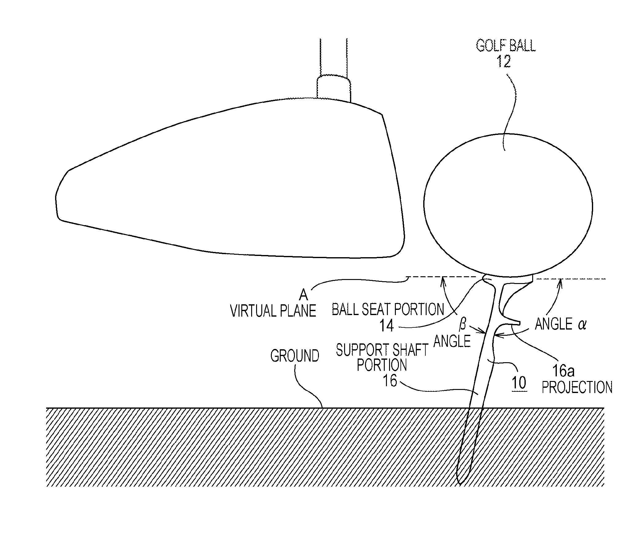
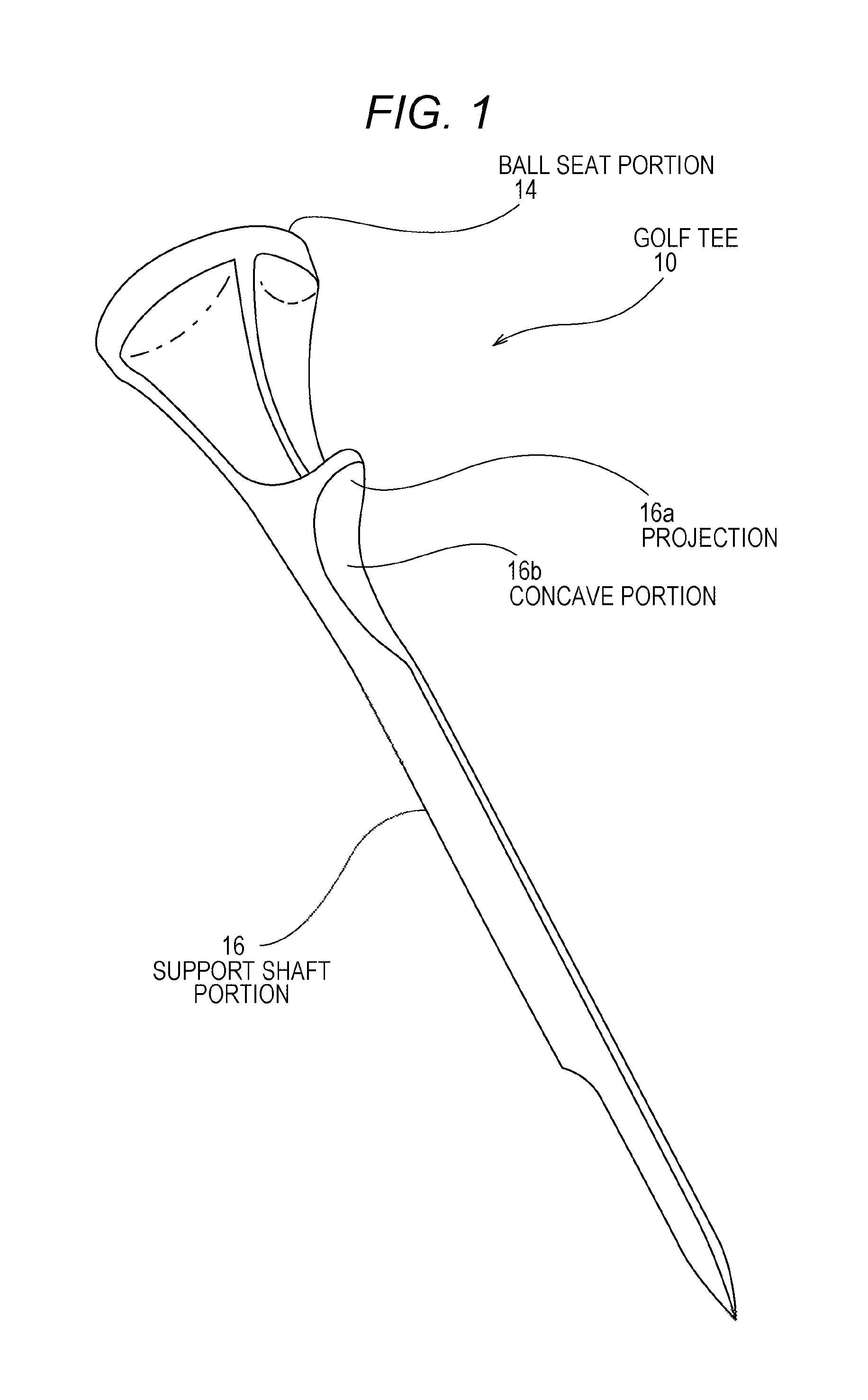
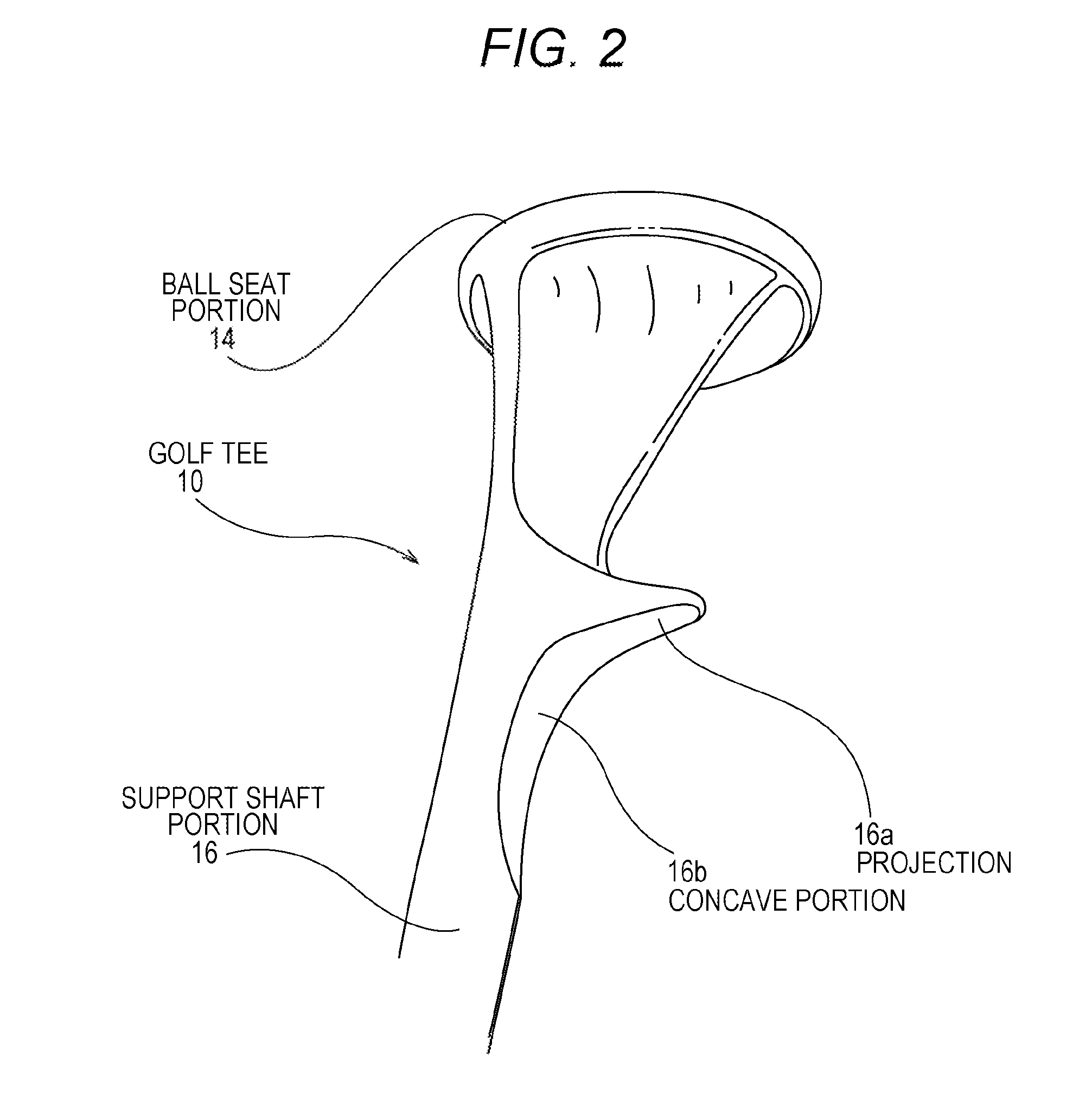
[0040]In the following, a golf tee according to an example of the present invention is described with reference to the drawings. FIG. 1 is a perspective view of a golf tee according to the example of the present invention. FIG. 2 is an expanded perspective view of the head part of the golf tee according to the example or the present invention. FIG. 3 is a side view of the golf tee according to the example of the present invention. FIG. 4 is a front view of the golf tee according to the example of the present invention. FIG. 5 is an explanatory diagram to conceptually describe a golf tee and golf ball according to the example of the present invention.

[0041]As illustrated in these figures, the golf tee 10 includes the ball seat portion 14 on which the golf ball 12 is placed, and the rod-shaped support shaft portion 16 formed downward from the bottom of the ball seat portion 14. The support shaft portion 16 includes a projection 16a that is projected and formed toward the side directio...


PUM


Abstract

A golf tee includes a ball seat portion on which a golf ball is placed; and a rod-shaped support shaft portion formed downward from the ball seat portion. The support shaft portion has a projection that is laterally formed on and projected from the support shaft portion. The ball seat portion and the support shaft portion are formed plane-symmetrically on a single plane including a central axis line of the support shaft portion and a point of the projection. In the single plane, a virtual plane including contact portion that contacts with a golf ball when the golf ball is placed on the ball seat portion and a central axis line of the support shaft portion form an obtuse angle on one side of the axis line and form an acute angle on the other side of the axis line.

Description

TECHNICAL FIELD[0001]The present invention relates to a golf tee that makes a player easily imagine a direction of hitting a golf ball, and reduces resistance of hitting the golf ball.BACKGROUND ART[0002]A golf tee holds a golf ball at a predetermined height position above the ground when a golf player hits a tee-shot. Conventionally, golf tees of various shapes, structures and materials have been proposed, sold and used.[0003]FIG. 7 is an explanatory diagram illustrating one example of a golf tee in the related art. This golf tee 10 includes a ball seat portion 14 on which a golf ball 12 is placed, and a rod-shaped support shaft portion 16 vertically formed downward from the bottom of the ball seat portion 14. Angle α formed by a virtual plane (shown with broken line A) and the support shaft portion 16 is a substantially right angle (substantially 90 degrees) as illustrated in FIG. 7. The virtual plane includes a contact portion on the ball seat portion 14. The contact portion cont...

Claims


Application Information

Patent Timeline
08 May 2014
Publication
US20140128180A1
IPC
A63B57/00; A63B57/19; A63B102/32
CPC
A63B57/0018; A63B57/19; A63B57/10
Inventors
IMAI, TAKEO