Implanted cardiac device for defibrillation

a cardioverter and implantable technology, applied in the field of conventional implantable cardioverterdefibrillators, can solve the problems of battery performance degradation, need for battery replacement, and unnecessary removal of icd components

Inactive Publication Date: 2014-05-08
THE BOARD OF TRUSTEES OF THE LELAND STANFORD JUNIOR UNIV
View PDF4 Cites 111 Cited by
  • Summary
  • Abstract
  • Description
  • Claims
  • Application Information

AI Technical Summary

Benefits of technology

The present invention provides an implantable medical device for delivering electrical cardiac therapy with a first and second implantable housing. The second housing contains electronic circuitry, a storage capacitor, and an electrode structure for evaluating and initiating electrical cardiac therapy. The second housing can be implanted at a different location in the body than the first housing, such as subcutaneously, within the vasculature, or within the pericardial space. The second housing can be in direct contact with the epicardium or positioned within a cavity in the body. The method of providing electrical cardiac therapy involves implanting the first housing and then the second housing at different locations in the body. The implantable structure can be adapted and configured for implantation within the pericardial space. The technical effects of the invention include improved delivery of electrical cardiac therapy and increased flexibility in implantation site.

Problems solved by technology

One ongoing challenge is degrading battery performance over time and the eventual need for battery replacement.
One shortcoming of the prior art is that the use of a single housing for both permanent components like capacitors and electronic circuitry with non-permanent components like batteries leads to unnecessary removal of ICD components that could otherwise remain implanted and operational.
The application of ICD shocks to surrounding tissue, nerves and muscle can be painful for patients.

Method used


Image

  • Implanted cardiac device for defibrillation
  • Implanted cardiac device for defibrillation
  • Implanted cardiac device for defibrillation

Examples


Embodiment Construction

[0042]According to Rahul Mehra, PhD and Paul DeGroot, MS, in an article entitled, “Where are we, and where are we heading in the device management of ventricular tachycardia / ventricular fibrillation?” there are several challenges for increasing the acceptance of ICD therapy. Among the challenges is to improve the technology, facilitating implant and follow up from the physician's perspective and lowering morbidity from the patient's perspective. The same article points out that patients want ICDs that are smaller, result in fewer shocks, have less pain associated with defibrillation, require minimal follow-up, and last a long time so that the devices to not require replacement (Heart Rhythm, Volume 4, No. 1, January 2007). As will become clear in the detailed description that follows, embodiments of the ICD system and components of the present invention address these challenges and patient desires.

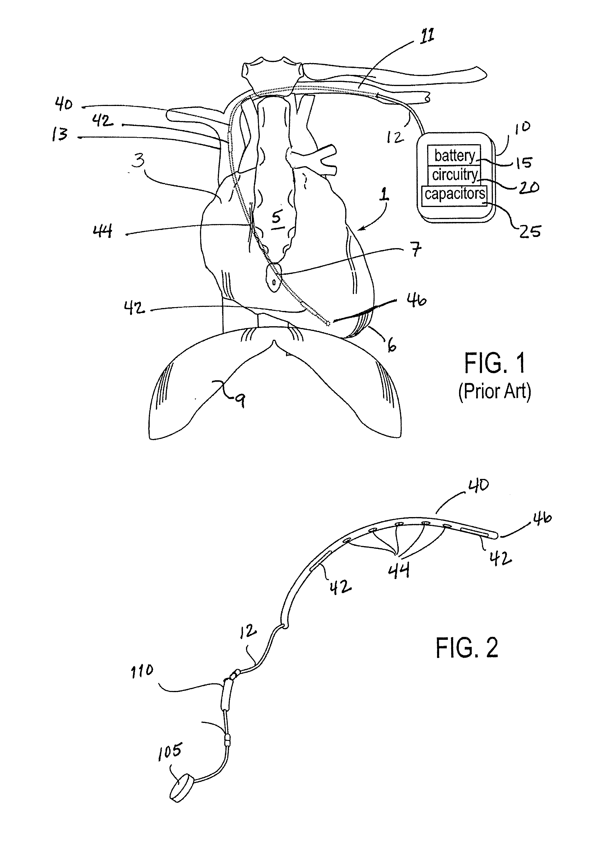
[0043]FIG. 2 illustrates an implantable medical device for delivering electrical cardi...


PUM


Abstract

An implantable medical device for delivering electrical cardiac therapy includes a first implantable housing containing a battery. There is also a second implantable housing separate from the first implantable housing and containing at least one of: electronic circuitry adapted to evaluate and initiate electrical cardiac therapy, a storage capacitor and an electrode structure comprising a sensing electrode, a pacing electrode and a therapy electrode. There is a method of providing electrical cardiac therapy by implanting a first housing containing a battery into a first implantation site within the body. Then, implant a second housing separate from the first housing into a second implantation site within the body. The second housing contains at least one of: electronic circuitry adapted to evaluate and initiate electrical cardiac therapy; a storage capacitor and an electrode structure comprising a sensing electrode, a pacing electrode and a therapy electrode.

Description

CROSS REFERENCE TO RELATED APPLICATIONS[0001]This application is a continuation of U.S. patent application Ser. No. 12 / 281,260 filed Nov. 25, 2008, titled “IMPLANTED CARDIAC DEVICE FOR DEFIBRILLATION,” now U.S. Pat. No. 8,630,710, which is a national stage application of International Application No. PCT / US2007 / 005515, filed Mar. 1, 2007, titled “IMPLANTED CARDIAC DEVICE FOR DEFIBRILLATION,” now Publication No. WO 2007 / 103262, which claims the benefit under 35 U.S.C. 119 of U.S. Provisional Patent Application No. 60 / 778,118 filed Mar. 1, 2006, titled “IMPLANTED CARDIAC DEVICE FOR DEFIBRILLATION,” each of which is incorporated herein by reference in its entirety.BACKGROUND[0002]FIG. 1 illustrates a conventional implantable cardioverter-defibrillator (ICD). An electrode structure 40 has been passed thought the subclavian vein 11 into the heart 1. Therapy electrodes 42 are used to deliver energy to shock the heart if and when abnormal cardiac activity is detected. Sensing and / or pacing...

Claims


Application Information

Patent Timeline
Patent Type & Authority Applications(United States)
IPC IPC(8): A61N1/37
CPCA61N1/37A61N1/0587A61N1/375A61N1/3756A61N1/3968A61N1/37518A61N1/37516A61N1/39622
Inventor KUMAR, UDAY N.WHITE, JOHN WARRENKNIGHT, JOSEPH ALLENAU-YEUNG, KIT YEE
Owner THE BOARD OF TRUSTEES OF THE LELAND STANFORD JUNIOR UNIV
Why Eureka
Try Eureka