

Test system and method for computer
a test system and computer technology, applied in the field of test system for computers, can solve the problems of difficult to determine which parts of the computer malfunction, inconvenient to determine whether or not the computer malfunctions,
- Summary
- Abstract
- Description
- Claims
- Application Information
AI Technical Summary
Benefits of technology
Problems solved by technology
Method used
Image

Examples
Embodiment Construction
[0010]The disclosure is illustrated by way of example and not by way of limitation in the figures of the accompanying drawings in which like references indicate similar elements. It should be noted that references to “an” or “one” embodiment in this disclosure are not necessarily to the same embodiment, and such references mean ‘at least one’.
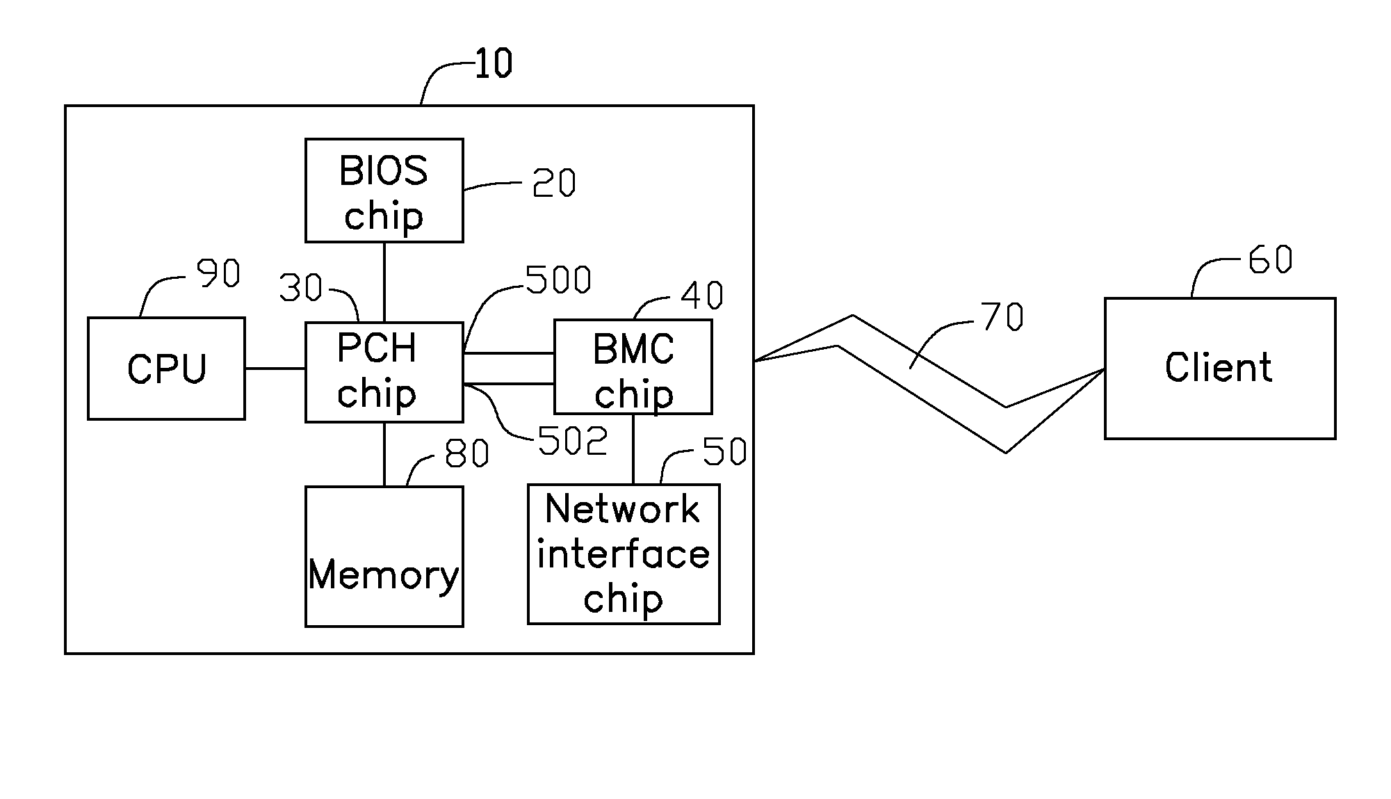
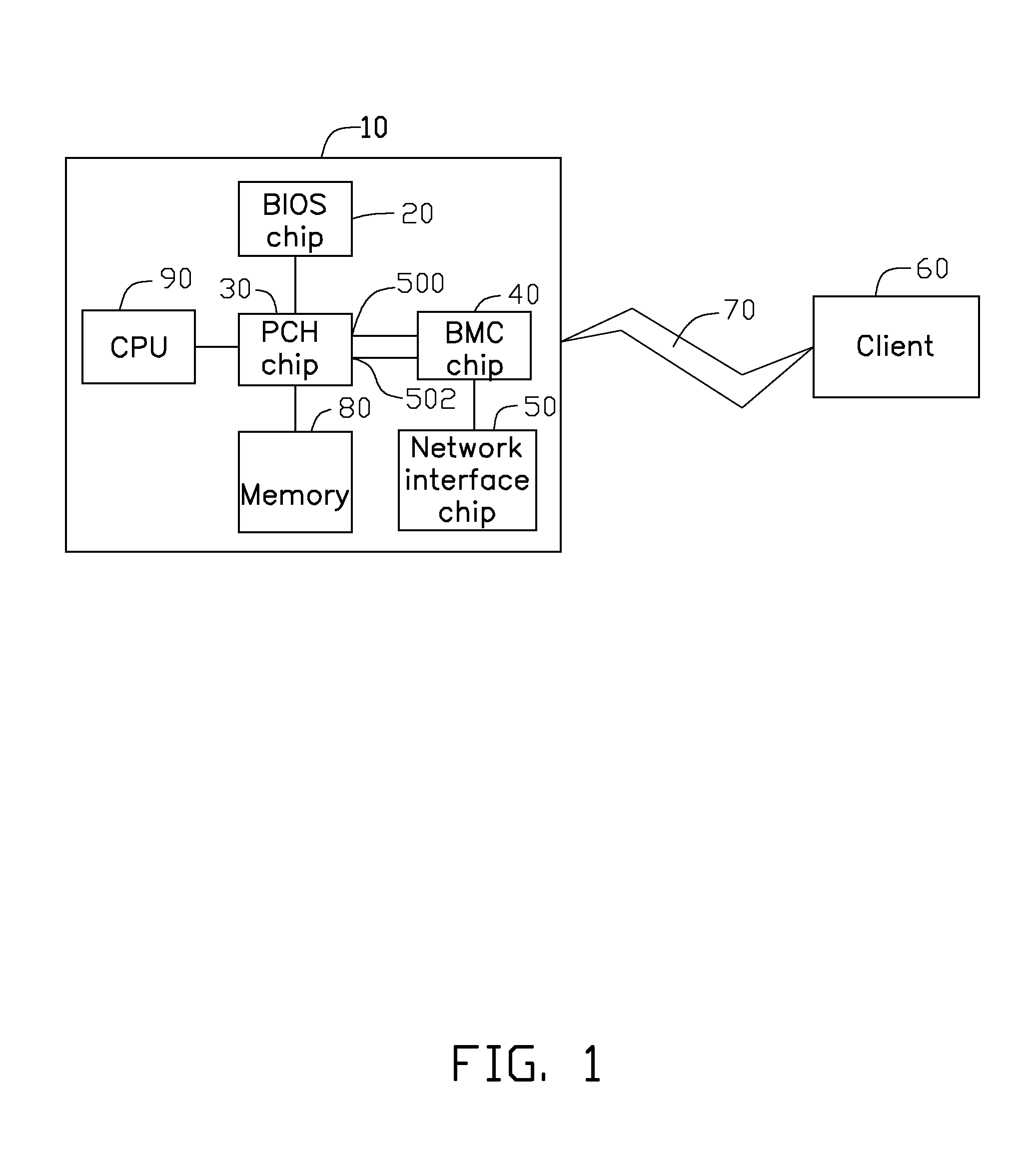
[0011]FIG. 1 illustrates an embodiment of a test system for a computer 10. The test system is configured to perform a test on a number of components of the computer 10 and output test results to a client 60 through a network 70. The test system includes a basic input / output system (BIOS) chip 20, a platform controller hub (PCH) chip 30, a baseboard management controller (BMC) chip 40, and a network interface chip 50. In the embodiment, the components to be tested include a central processing unit (CPU) 90 and a memory 80. The PCH chip 30 outputs state signals to the BMC chip 40 through corresponding general purpose input / output (GPIO) pins. The...
PUM
 Abstract
Description
Claims
Application Information