Electric junction box

Active Publication Date: 2014-05-15
YAZAKI CORP
View PDF6 Cites 8 Cited by
  • Summary
  • Abstract
  • Description
  • Claims
  • Application Information

AI Technical Summary

Benefits of technology

The invention is an electric junction box that has a case with multiple chambers for holding parts. The case is designed to have better insulation to prevent overheating between neighboring chambers without making the case bigger.

Problems solved by technology

However, because the gap or clearance between the two walls 206a and 206b is very small or slight, the resulting thermal insulation effect is not thus advantageous.

Method used


Image

  • Electric junction box
  • Electric junction box
  • Electric junction box

Examples


Embodiment Construction

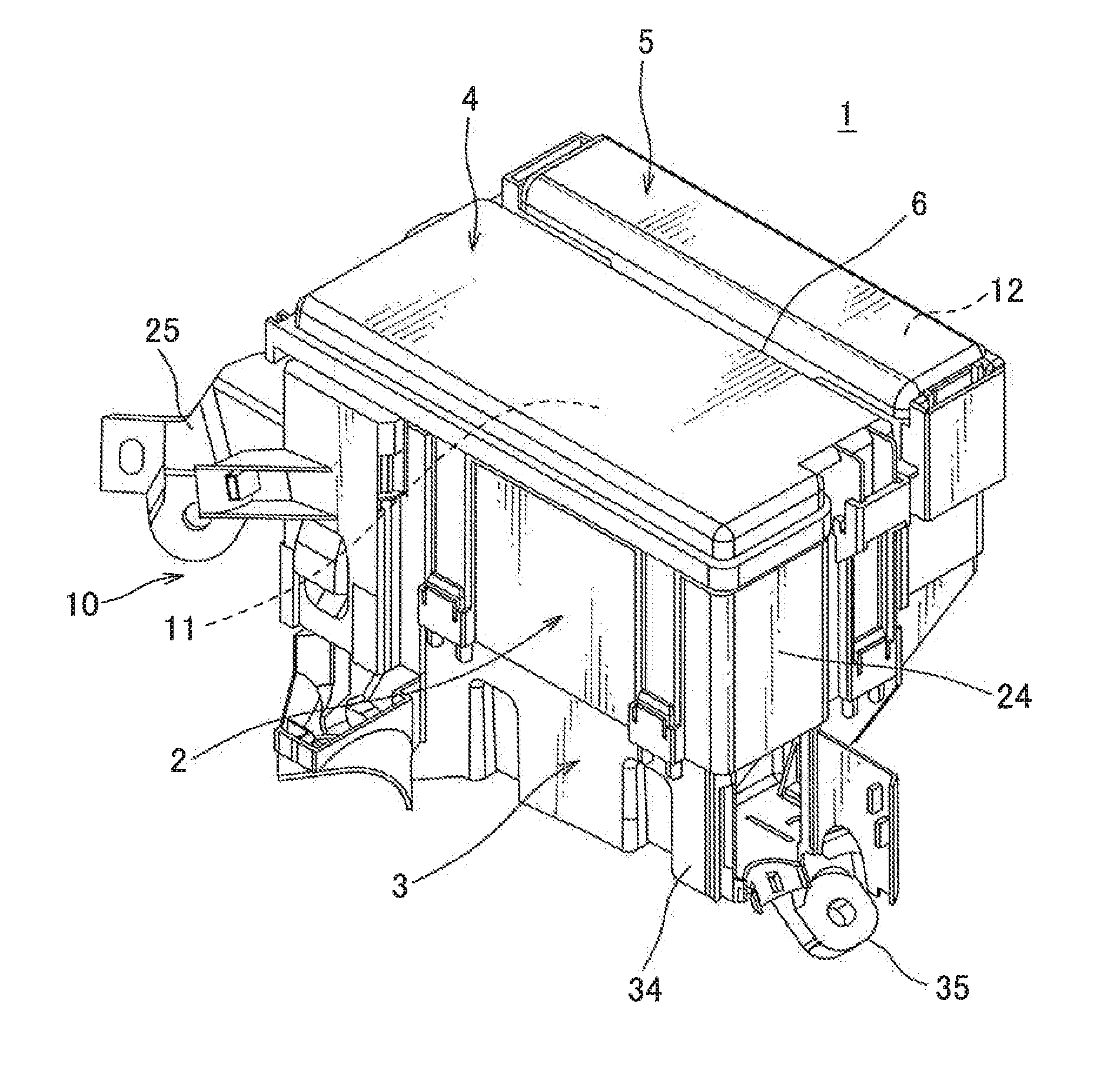
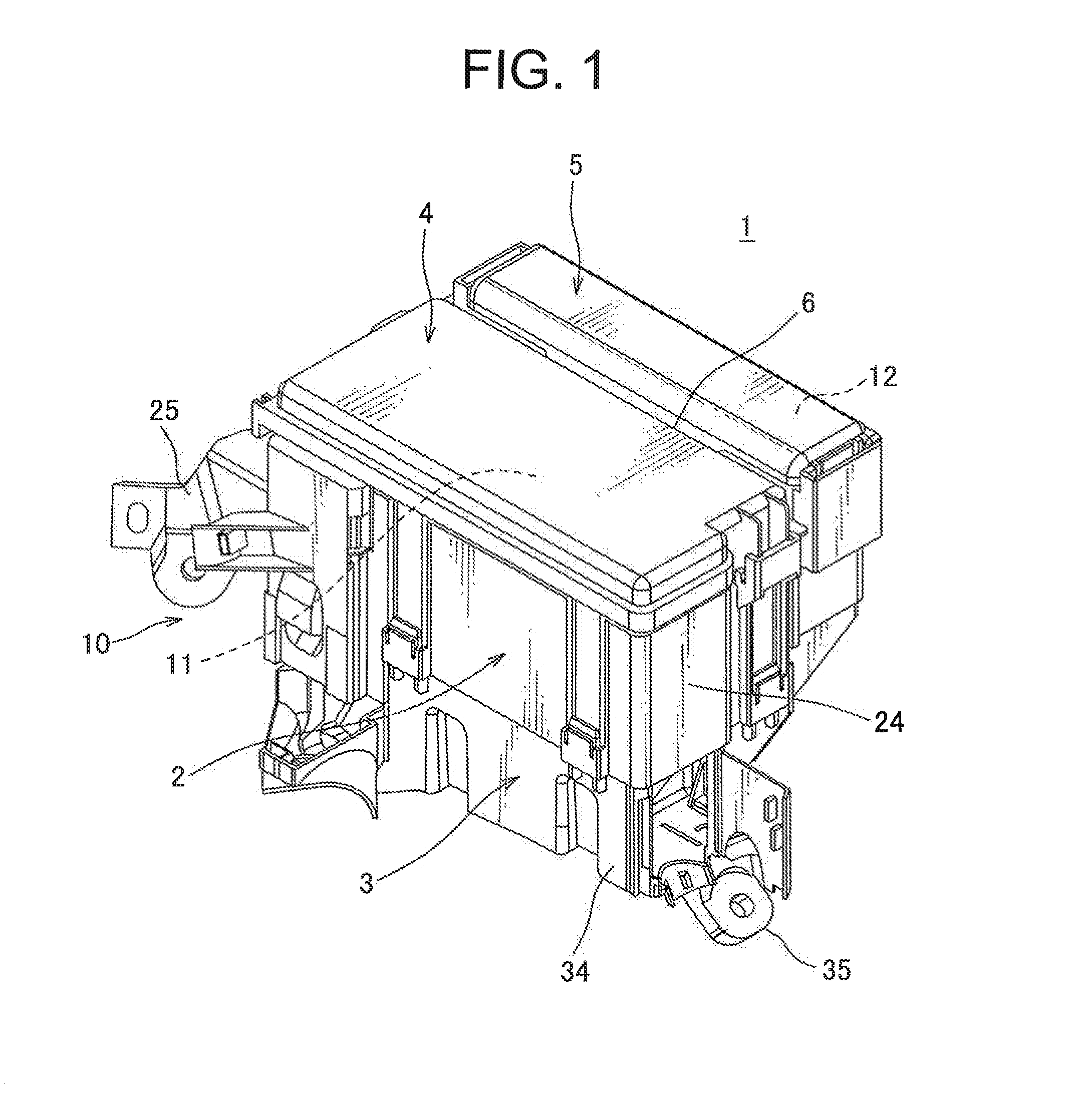
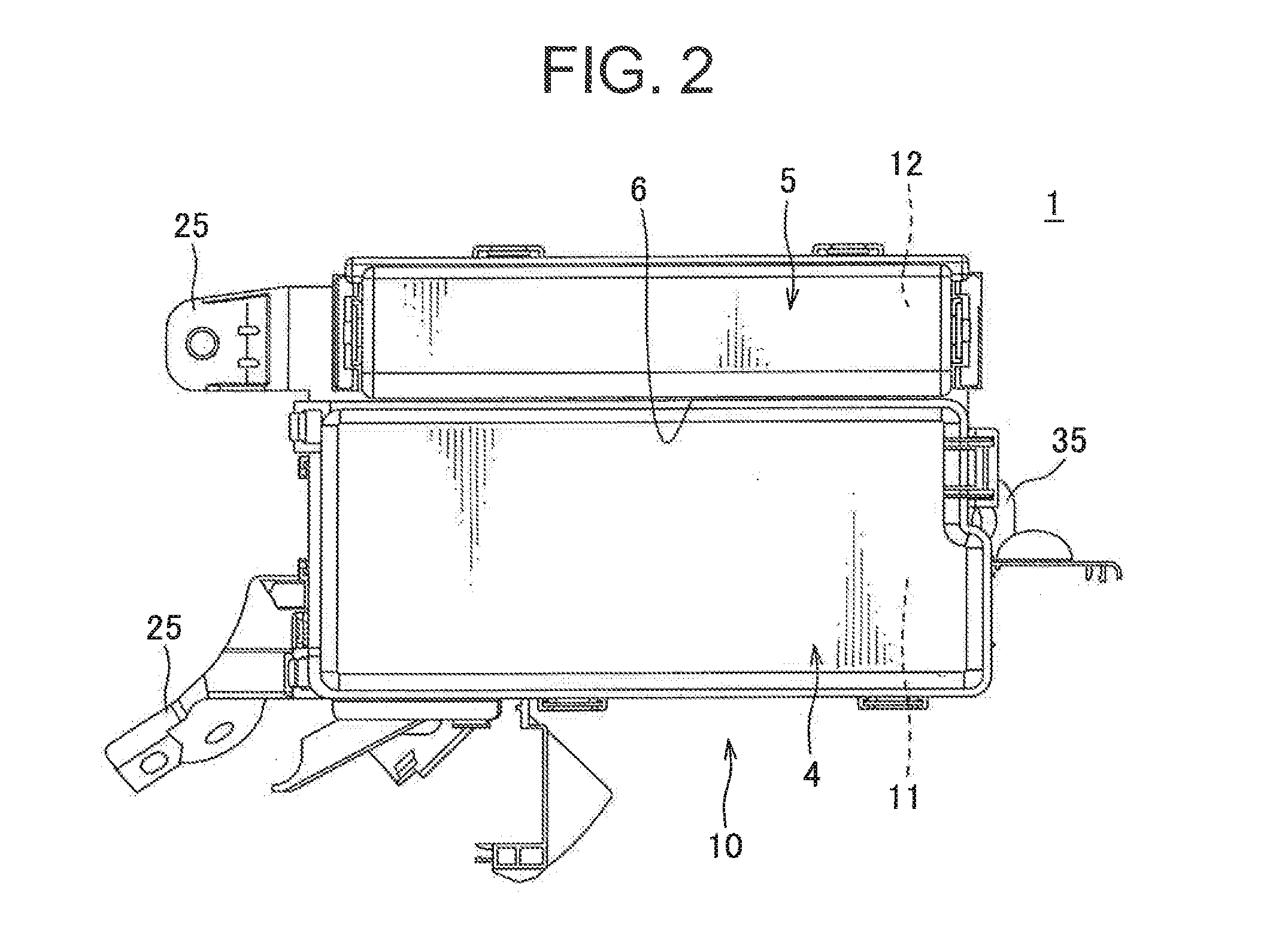
[0024]One embodiment of an electric junction box in accordance with the invention will be described with reference to FIGS. 1-7. The electric junction box in accordance with the invention is suited to be mounted in a vehicle and is configured to supply electric power to an electronic device mounted in the vehicle and transfer signal to the electronic device.

[0025]With reference to FIGS. 1 and 2, the one embodiment of the electric junction box 1 has a case 10 in which a first part-receiving chamber 11 and a second part-receiving chamber 12 are disposed adjacent to each other. Referring to FIGS. 4 and 6, the case 10 includes a case body 2, a plurality of cassette blocks 7 coupled to the inside of the case body 2 to at least partly define a first part-receiving chamber 11, a first upper cover 4 coupled to the upper end of the case body 2 to at least partly define the first part-receiving chamber 11, a second upper cover 5 coupled to the upper end of the case body 2 to at least partly d...


PUM


Abstract

The invention provides an electric junction box with an enhanced thermal insulation between neighboring part-receiving chambers without causing excessive increase in the size of a case. In order to attain the objective, there is provided an electric junction box, which includes a case provided with a case body, a lower cover coupled to the lower end of the case body, and first and second upper covers and coupled to the upper end of the case body. The case includes neighboring first and second part-receiving chambers and. A through-hole is located between the first and second part-receiving chambers and extends from an upper end of the case to a lower end of the case. The through-hole has an enlarging portion, which is disposed at a lower end thereof and has increasing cross-sectional area as approaching to the lower end of the through-hole.

Description

CROSS-REFERENCE TO RELATED APPLICATIONS[0001]This application claims priority from Japanese Patent Application No. 2012-249864 filed on Nov. 14, 2012, which is incorporated herein by reference.BACKGROUND OF THE INVENTION[0002]1. Field of the Invention[0003]The invention relates to an electric junction box which is adapted to be mounted in a vehicle.[0004]2. Background of the Invention[0005]FIG. 8 is an exploded view of a conventional electric junction box. See JP 2006-121880 A. A case 202 is a case body 203, an upper surface of which is opened, a first cover 204 and a second cover 205 disposed such that the upper surface of the case body 203 is closed.[0006]The case body 203 has a partition wall 206 therein, which divides the interior space of the case body 203 into two part-receiving chambers 207a and 207b. The partition wall 206 is defined by two walls 206a and 206b which are slightly spaced apart from each other. Any fluid such as water which penetrates into a gap or clearance be...

Claims


Application Information

Patent Timeline
IPC IPC(8): H02G3/08
CPCH02G3/088
Inventor HIRASAWA, HITOSHIIMAIZUMI, YOSHIHITO
Owner YAZAKI CORP
Why Eureka
Try Eureka