Working device and method

Active Publication Date: 2014-05-15
KUKA SYSTEMS
View PDF4 Cites 10 Cited by
  • Summary
  • Abstract
  • Description
  • Claims
  • Application Information

AI Technical Summary

Benefits of technology

[0005]The object of the present invention is to provide a better working

Problems solved by technology

Such screwing robots require a great construction effort and a lar

Method used


Image

  • Working device and method
  • Working device and method
  • Working device and method

Examples


Example

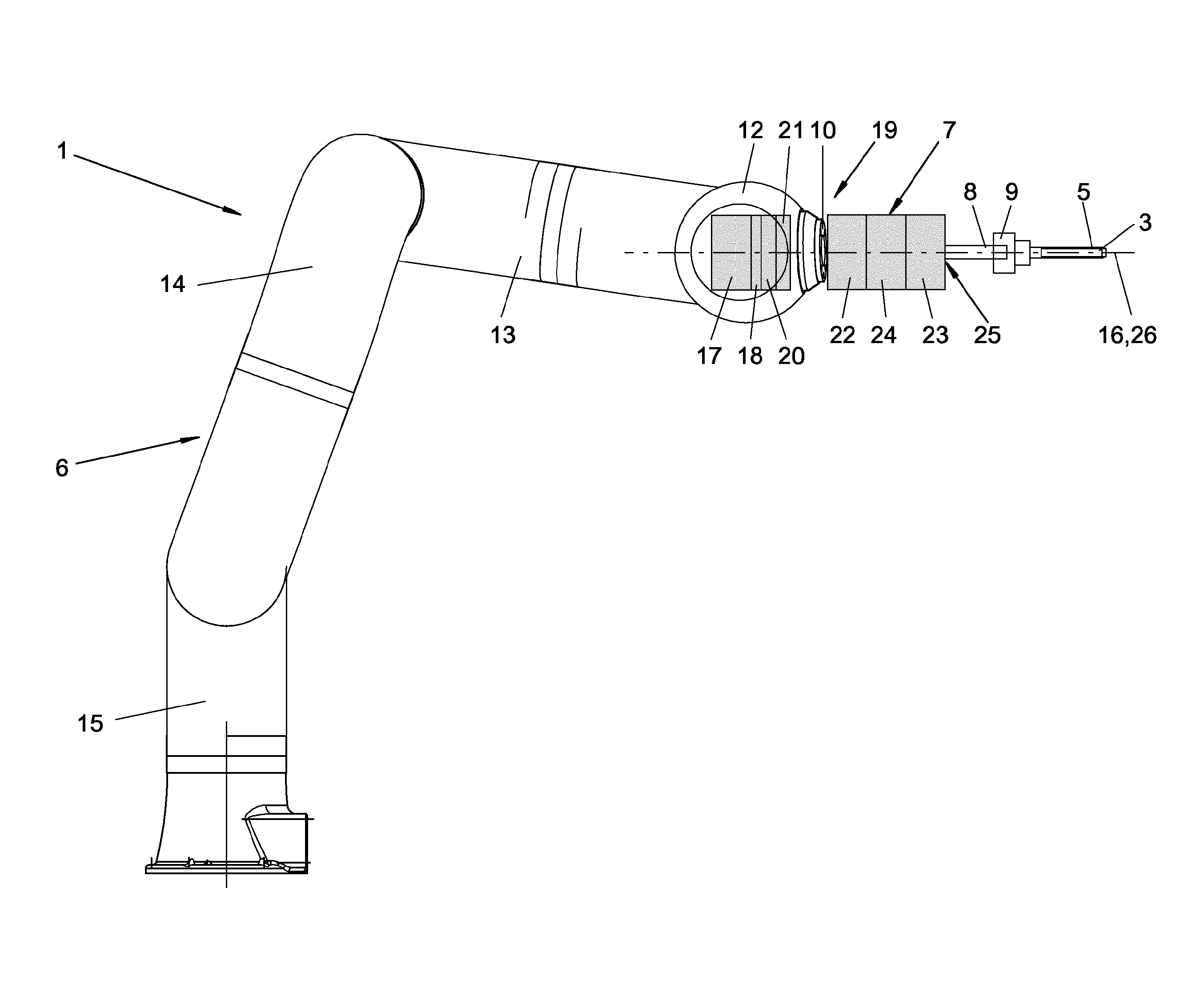
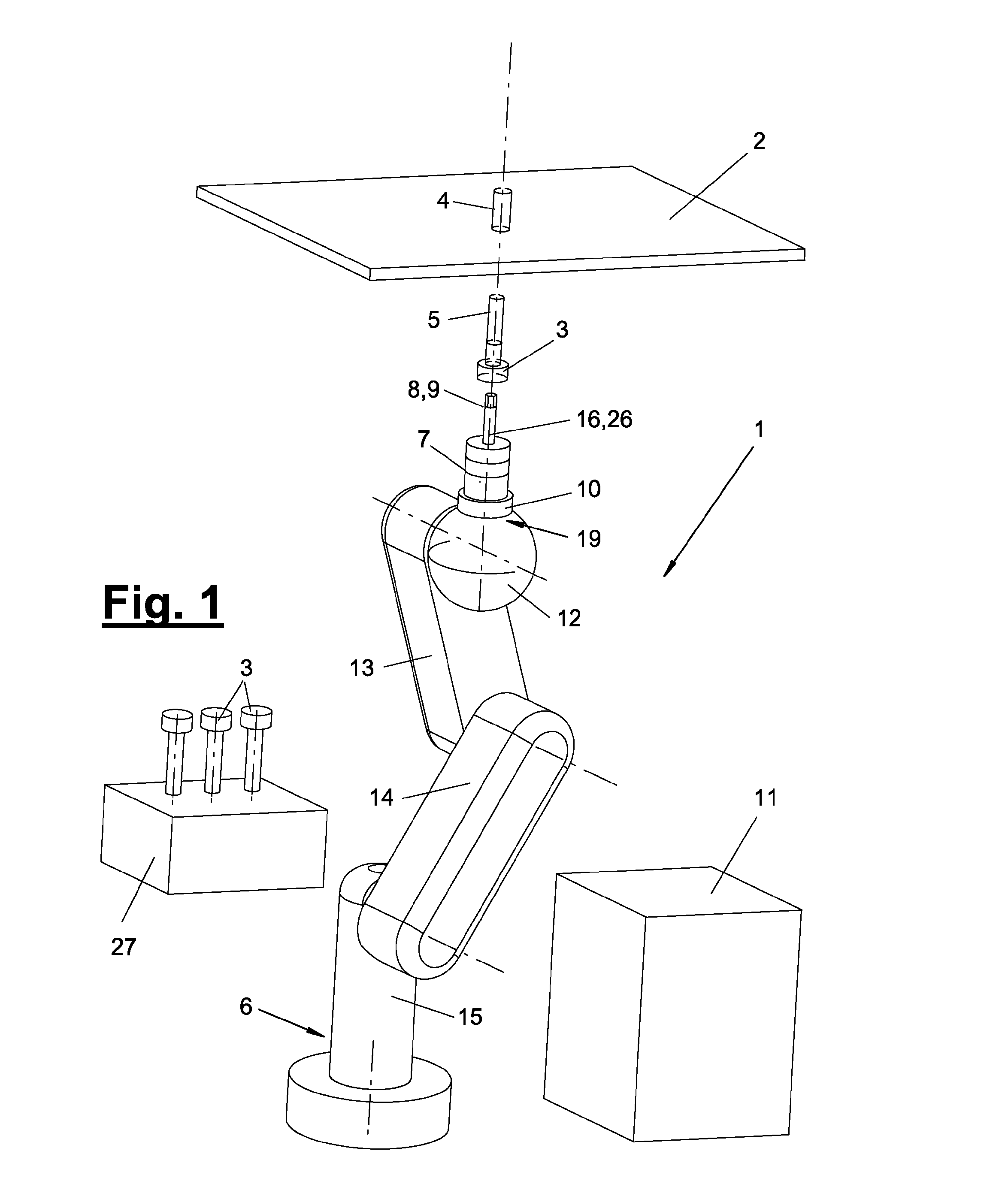
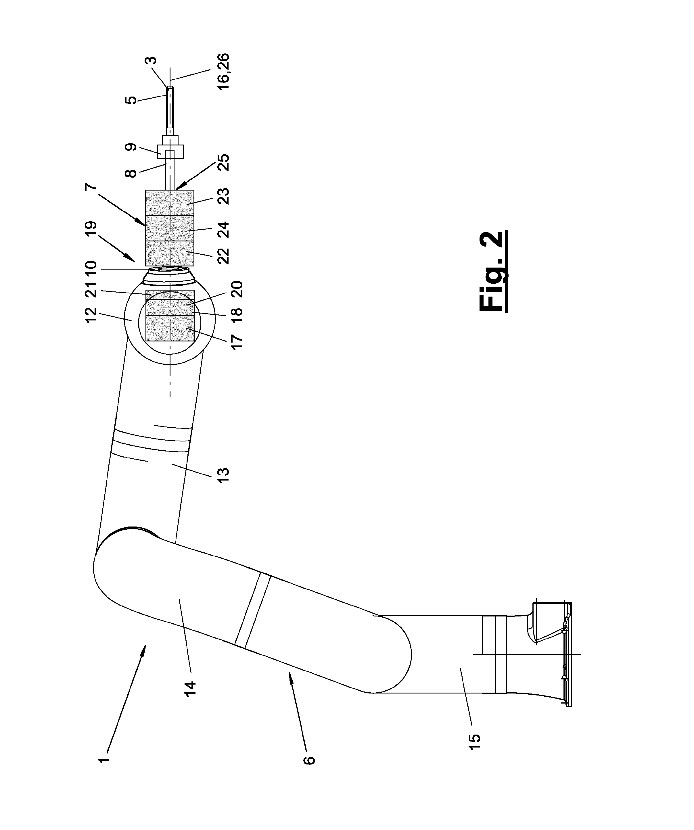
[0047]Referring to the drawings in particular, the present invention pertains to a working device (1) for the rotational joining and / or rotational loosening of rotary parts (3). The present invention pertains, furthermore, to a rotational joining and loosening method and to a method for using such a working device (1).

[0048]A rotary part (3) is connected to a rotary receptacle (4) during rotational joining and / or loosening. An additional function with clamping, fastening or the like of another part may be associated herewith. A relative motion is carried out during rotational joining and / or loosening between the rotary part (3) and the rotary receptacle (4), which comprises at least one rotation and possibly a linear motion, e.g., an axial feeding or retracting motion. The exemplary embodiments explained below show a rotational joining process, which is designed as a screwing process. The rotary part (3) is a screwed part. It may be, e.g., the screw shown in the drawings with a shan...


PUM

PropertyMeasurementUnit
Forceaaaaaaaaaa
Resilienceaaaaaaaaaa
Torqueaaaaaaaaaa

Abstract

A screwing device (1) and a screwing method use a multi-member (12, 13, 14, 15) robot (6) having a driven rotational axis. The robot (6), on its last member (12), carries a rotational device (7) with a rotational tool (8). The rotational device is driven independently and is provided and designed for rapidly screwing a rotating part (3) on or off. The screwing tightening or untightening of the rotating part (3) is performed by the robot (6) and in particular by the robot end member (12).

Description

CROSS REFERENCE TO RELATED APPLICATIONS[0001]This application is a United States National Phase Application of International Application PCT / EP2012 / 062972 filed Jul. 4, 2012 and claims the benefit of priority under 35 U.S.C. §119 of German Utility Model Application DE 20 2011 103 223.3 filed Jul. 8, 2011, the entire contents of which are incorporated herein by reference.FIELD OF THE INVENTION[0002]The present invention pertains to a working device and a method for rotational joining and / or for rotational loosening, especially a screwing device, for the rotational joining and / or loosening of rotary parts, especially screws or nuts, with a multi-member robot with a driven axis of rotation, wherein the robot carries on its end member an independently driven rotating device with a rotating tool.BACKGROUND OF THE INVENTION[0003]Screwing robots, which consist of a conventional articulated-arm robot, which carries at its end member, e.g., a multiaxially movable robot hand, a screwing devic...

Claims


Application Information

Patent Timeline
IPC IPC(8): B25J9/16
CPCB25J9/1694B25J9/1633B25J15/0019Y10T29/53Y10T29/49826
Inventor MAISCHBERGER, JOHANNNEIDER, REINHOLDHOENE, ALBRECHT
Owner KUKA SYSTEMS
Why Eureka
Try Eureka