Adhesive dispensing system and method including a pump with integrated diagnostics

Active Publication Date: 2014-05-22
NORDSON CORP
View PDF17 Cites 21 Cited by
  • Summary
  • Abstract
  • Description
  • Claims
  • Application Information

AI Technical Summary

Benefits of technology

[0011]Generally speaking, the diagnostic processes are configured to identify error states or fault conditions based on the collected information, and then provide an indication to an operator of the error state or fault condition. For example, providing the indication may include producing a message on a display screen or illuminating an indicator light or tone that indicates an error state or fault condition has been identified. These error states and fault conditions may be detected without directly measuring pressure within the pump with a pressure transducer, so the additional diagnostic capabilities are provided with minimal additional expense and maintenance requirements.
[0012]In another aspect, the pump is a piston pump with a piston coupled to a pump rod. Operating the pump is performed by actuating at least one solenoid to supply pressurized air to one side of the piston, thereby moving the piston and the pump rod from a first end condition to a second end condition. The operating state of the solenoid(s) is switched so that the pressurized air is supplied to the other side of the piston to move the piston and pump rod back to the first end condition. It will be understood that the solenoid(s) could be replaced by a spool valve or some other air valve in other embodiments. The pump rod moves liquid adhesive during the movement between the first and second end conditions, thereby pumping liq

Problems solved by technology

Furthermore, pumps can develop various conditions such as leaking seals or inoperative valves that interfere with the pumping operation.
Conventional piston pumps typically do not include sensors or monitoring devices that can detect these conditions, and therefore, the pumps must usually be damaged or signific

Method used


Image

  • Adhesive dispensing system and method including a pump with integrated diagnostics
  • Adhesive dispensing system and method including a pump with integrated diagnostics
  • Adhesive dispensing system and method including a pump with integrated diagnostics

Examples


Example

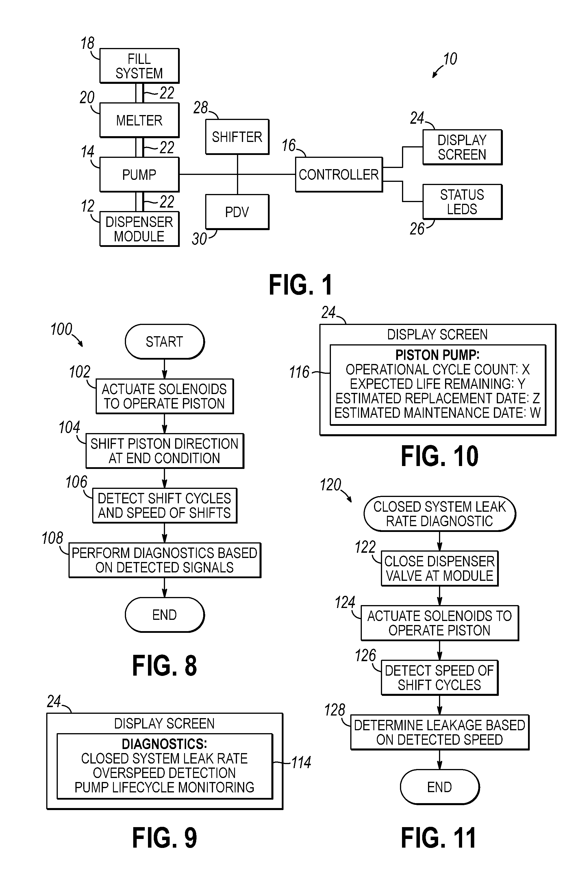
[0030]Referring to FIG. 1, an adhesive dispensing system 10 in accordance with one embodiment of the invention is shown. The adhesive dispensing system 10 is configured to deliver liquid adhesive from a source of liquid adhesive to a dispenser module 12 using a pump 14, such that the liquid adhesive may be dispensed on demand at the dispenser module 12. Advantageously, the controller 16 that operates the pump 14 is configured to collect information regarding the operational cycles performed by the pump 14. This information is based on sensed movements of the pump 14 and may be used to perform one or more diagnostics pertaining to the pump 14 or to the adhesive dispensing system 10 as a whole. These diagnostic processes may be used to detect error states and fault conditions of the pump 14 such as high leak rates and overspeed conditions, thereby enabling maintenance to be performed before these error states cause significant component damage or adhesive loss. Furthermore, the sensor...


PUM


Abstract

An adhesive dispensing system includes a pump and at least one sensor positioned to sense movements of a component of the pump and produce signals based on the sensed movements. The dispensing system also includes a controller operating the pump and communicating with the at least one sensor to collect information regarding operational cycles of the pump based on the signals. As a result, one or more diagnostic processes are enabled at the controller during operation of the adhesive dispensing system. These diagnostic processes may include a leak rate test for the dispensing system, an overspeed detection test for the pump, and expected life cycle monitoring of the pump or other components.

Description

CROSS-REFERENCE TO RELATED APPLICATION[0001]This application claims the benefit of U.S. Provisional Patent Application Ser. No. 61 / 727,924, filed on Nov. 19, 2012 (pending), the disclosure of which is incorporated by reference herein in its entirety.FIELD OF THE INVENTION[0002]The present invention generally relates to an adhesive dispensing system and more particularly, adhesive dispensing systems and methods using a piston pump to move adhesive toward an outlet.BACKGROUND[0003]A conventional dispensing system for supplying heated adhesive (i.e., a hot-melt adhesive dispensing system) generally includes an inlet for receiving adhesive materials in solid or semi-solid form, a melter in communication with the inlet for heating and / or melting the adhesive materials, an outlet in communication with the melter for receiving the heated adhesive from the melter, and a pump in communication with the melter and the outlet for driving and controlling the dispensation of the heated adhesive t...

Claims


Application Information

Patent Timeline
IPC IPC(8): F04B49/00
CPCB05B12/00B05C11/1002B05C5/0225F04B9/125F04B49/065F04B2201/0207F04B2201/02071F04B49/00F04B19/16F04B51/00
Inventor ESTELLE, PETER W.
Owner NORDSON CORP
Why Eureka
Try Eureka