
Light transport consistent scene simplification within graphics display system

Active Publication Date: 2014-01-23
NVIDIA CORP
View PDF0 Cites 2 Cited by
  • Summary
  • Abstract
  • Description
  • Claims
  • Application Information

AI Technical Summary

Benefits of technology

The present invention is a computer graphics method for creating a simplified scene representation that is consistent with the original three-dimensional scene. This method involves casting a plurality of rays towards the scene, constructing a simplified representation of the scene, and adjusting the simplified representation to match the original scene. This process allows for the creation of a high-quality image that accurately represents the original scene.

Problems solved by technology

However, while creating a simplified representation is fast and automatic, there is no guarantee that the obtained simplified representation faithfully represents the original three dimensional scene.
Scene misrepresentations due to simplification can lead to unwanted artifacts in rendered images.

Method used


Image

  • Light transport consistent scene simplification within graphics display system
  • Light transport consistent scene simplification within graphics display system
  • Light transport consistent scene simplification within graphics display system

Examples


Embodiment Construction

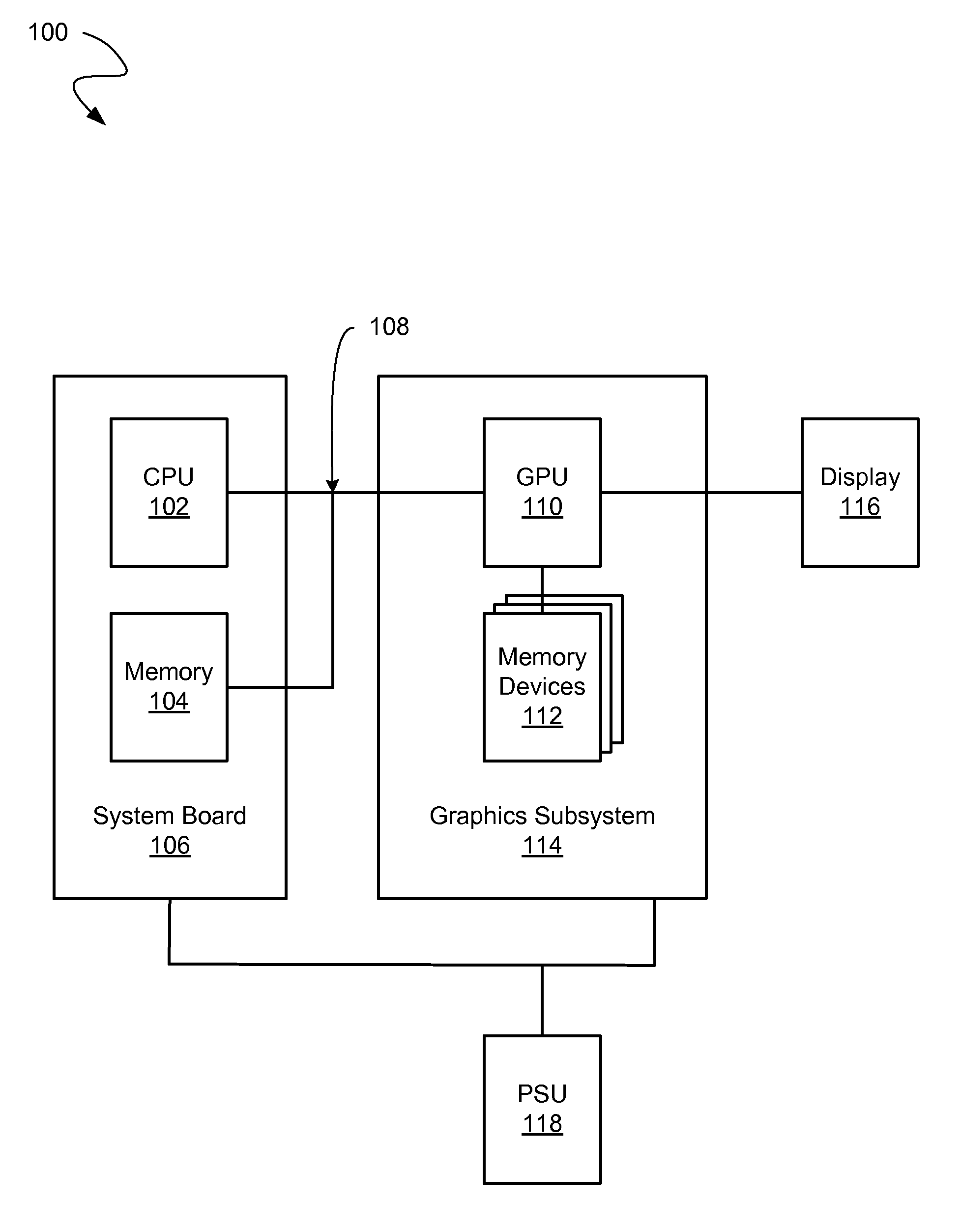
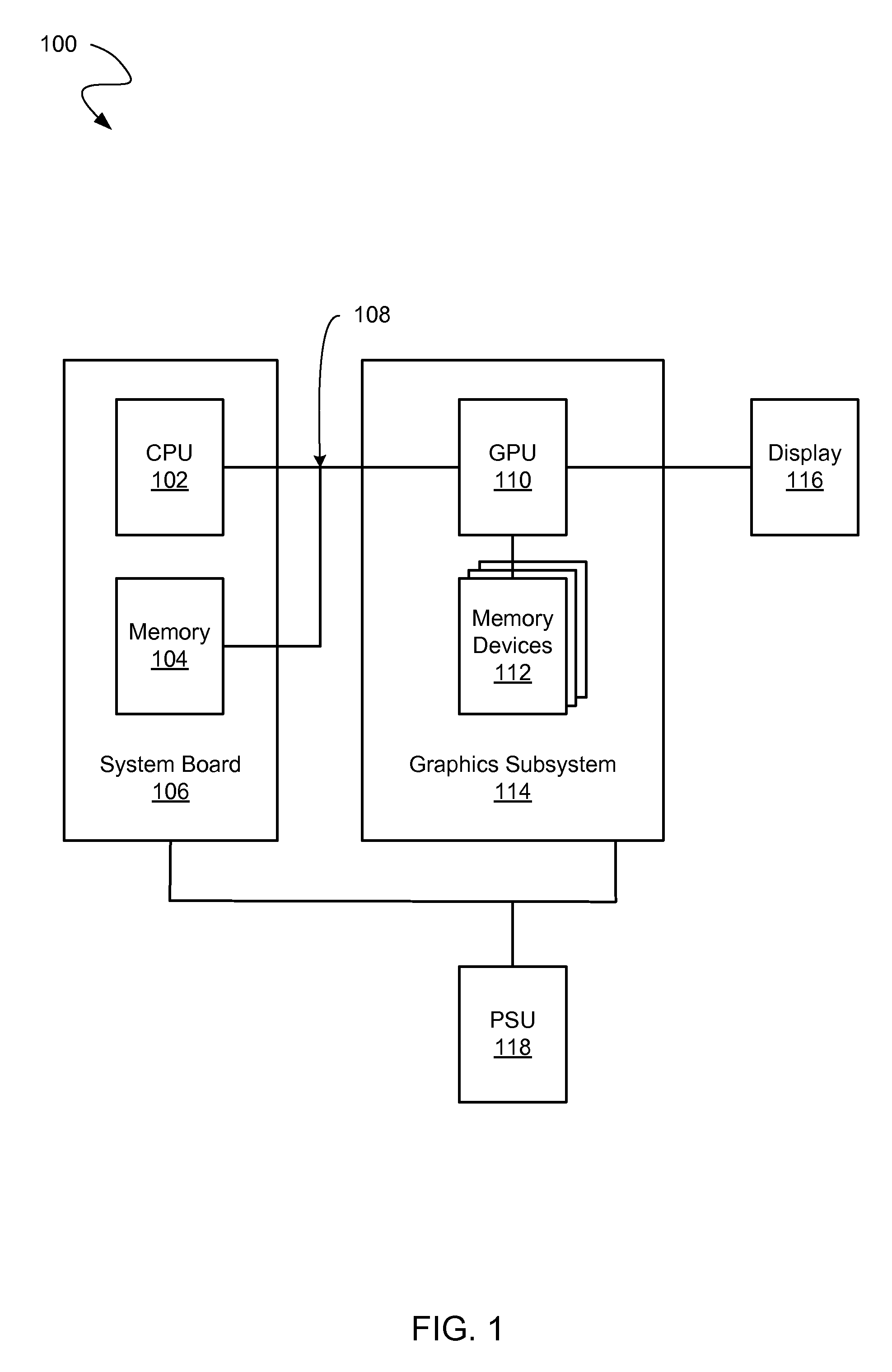
[0013]Reference will now be made in detail to embodiments of the present invention, examples of which are illustrated in the accompanying drawings. While the present invention will be discussed in conjunction with the following embodiments, it will be understood that they are not intended to limit the present invention to these embodiments alone. On the contrary, the present invention is intended to cover alternatives, modifications, and equivalents which may be included with the spirit and scope of the present invention as defined by the appended claims. Furthermore, in the following detailed description of the present invention, numerous specific details are set forth in order to provide a thorough understanding of the present invention. However, embodiments of the present invention may be practiced without these specific details. In other instances, well-known methods, procedures, components, and circuits have not been described in detail so as not to unnecessarily obscure aspect...


PUM


Abstract

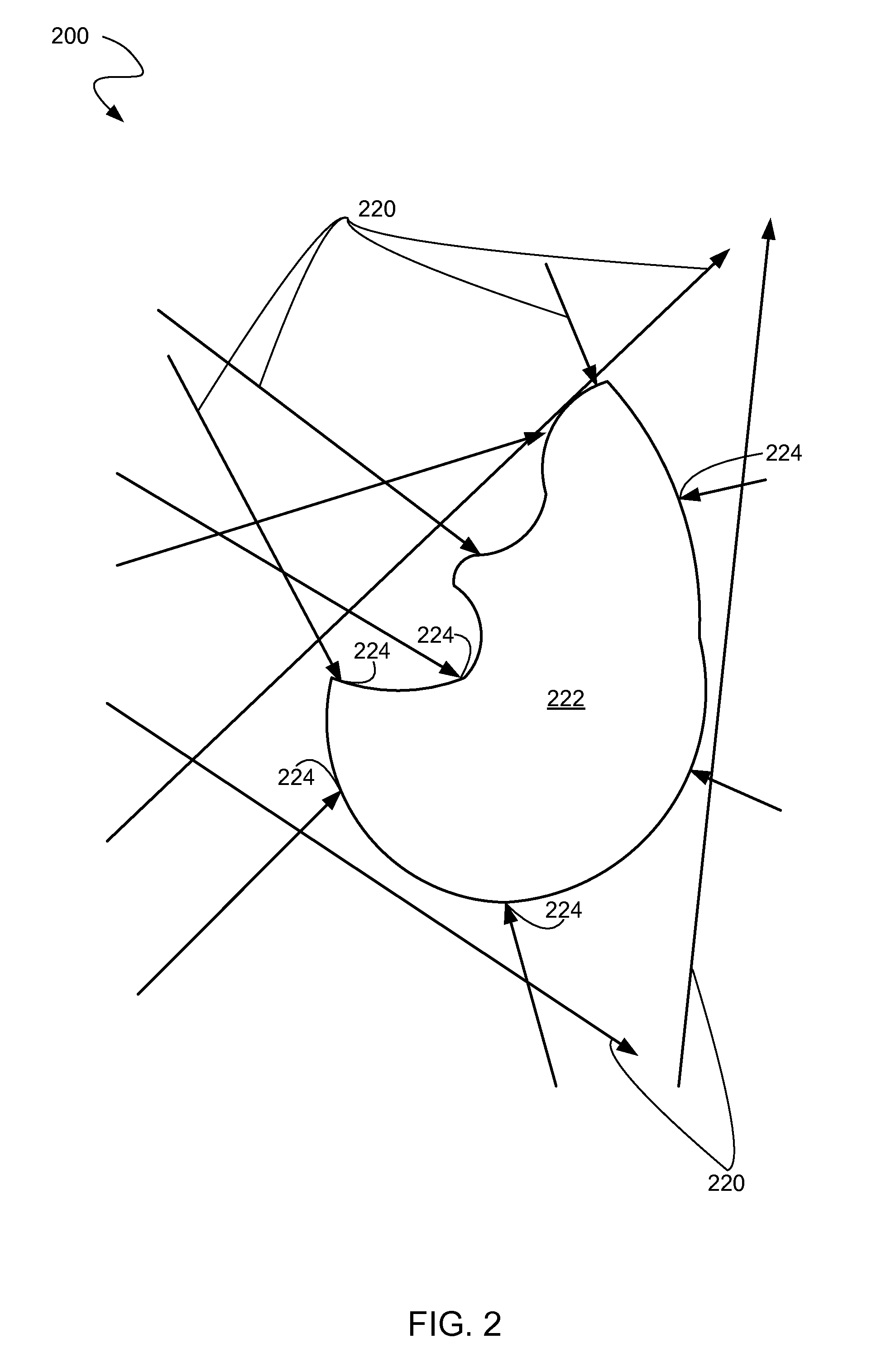
Method including casting a first plurality of rays towards an original 3-D scene comprising objects with object surfaces. Method also includes constructing a simplified representation of the original 3-D scene and adjusting the simplified representation to be consistent with the original 3-D scene. Simplified representation is adjusted by using known rays and object surface intersections obtained from the casting, to produce an adjusted simplified representation. Method further includes steps for rendering a high quality image: casting a second plurality of rays toward the adjusted simplified representation and testing the second plurality of rays for points of intersection with the object surfaces within the adjusted simplified representation, estimating incoming light within the adjusted simplified representation at the points of intersection with the object surfaces, examining material properties of the object surfaces, and calculating a color and light intensity for a plurality of pixels associated with the second plurality of rays.

Description

CROSS-REFERENCE TO RELATED APPLICATION[0001]This application is related to patent application, “SURFACE CLASSIFICATION FOR POINT-BASED RENDERING WITHIN GRAPHICS DISPLAY SYSTEM,” concurrently filed with this application, with attorney docket number NVID-P-HE-12-0079-US1, which is herein incorporated by reference in its entirety.BACKGROUND OF THE INVENTION[0002]Light transport algorithms based on ray tracing are used to sample a three dimensional scene and its illumination by casting rays within the scene. Typically, a large number of rays are required for high quality rendering, i.e. with an acceptable noise level. Because of this complexity, it is often beneficial to perform parts of lighting computations using a simplified representation of the three dimensional scene. Typical simplified representations are created using a standard k-nearest neighbor search to adapt to the local density of ray endpoints and derive a radius for each one. However, while creating a simplified represen...

Claims


Application Information

Patent Timeline
IPC IPC(8): G06T15/50
CPCG06T15/06G06T15/506
Inventor AILA, TIMO OSKARILEHTINEN, JAAKKO TAPANILAINE, SAMULI MATIAS
Owner NVIDIA CORP
Learn More