Imaging system and method

Pending Publication Date: 2021-01-07
3D OSCOPY LTD
View PDF0 Cites 0 Cited by
  • Summary
  • Abstract
  • Description
  • Claims
  • Application Information

AI Technical Summary

Benefits of technology

The invention provides a way to capture images in three dimensions without the need to move or manipulate the device. It uses a reflective optic that allows for imaging in places that are inaccessible to conventional refractive optic. The technology offers a wide panoramic field of view and is suitable for use in endoscopy applications. It is compact and efficient, making it suitable for imaging inside restricted spaces. Overall, the technology improves the speed, accuracy, and ease of imaging procedures.

Problems solved by technology

Whilst readily available and relatively inexpensive, simple endoscopes or borescopes of this kind run the risk of not seeing a potentially relevant target due to the narrow field of view.
However, endoscopes, borescopes and other similar imaging devices are still restricted by the angular view and the data that is obtainable using them.
This may be uncomfortable for the patient or operator and the endoscopy process may take longer which is undesirable because it prolongs or increases the discomfort and cost of endoscopy.
However, this requires additional mechanisms to change the direction and prolongs the procedure and / or increases the discomfort.
However, this results in a more bulky endoscope and with views limited by structural parts.
Endoscopes contain complex and precision optical components and efforts to date to try to increase their capabilities have led to devices that have become more complex and expensive and which are still restricted by the angular view and the data that is obtainable using them.

Method used


Image

  • Imaging system and method
  • Imaging system and method
  • Imaging system and method

Examples


Embodiment Construction

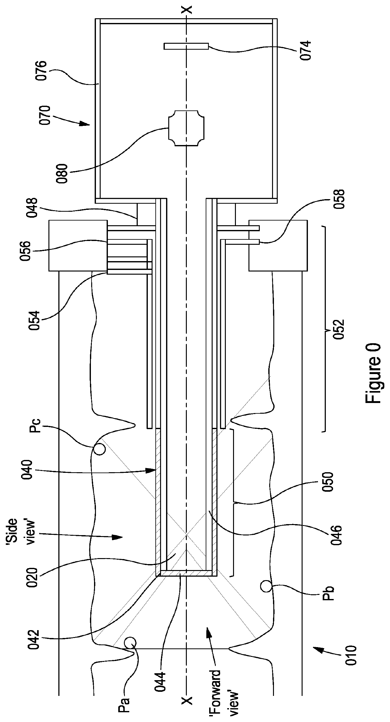
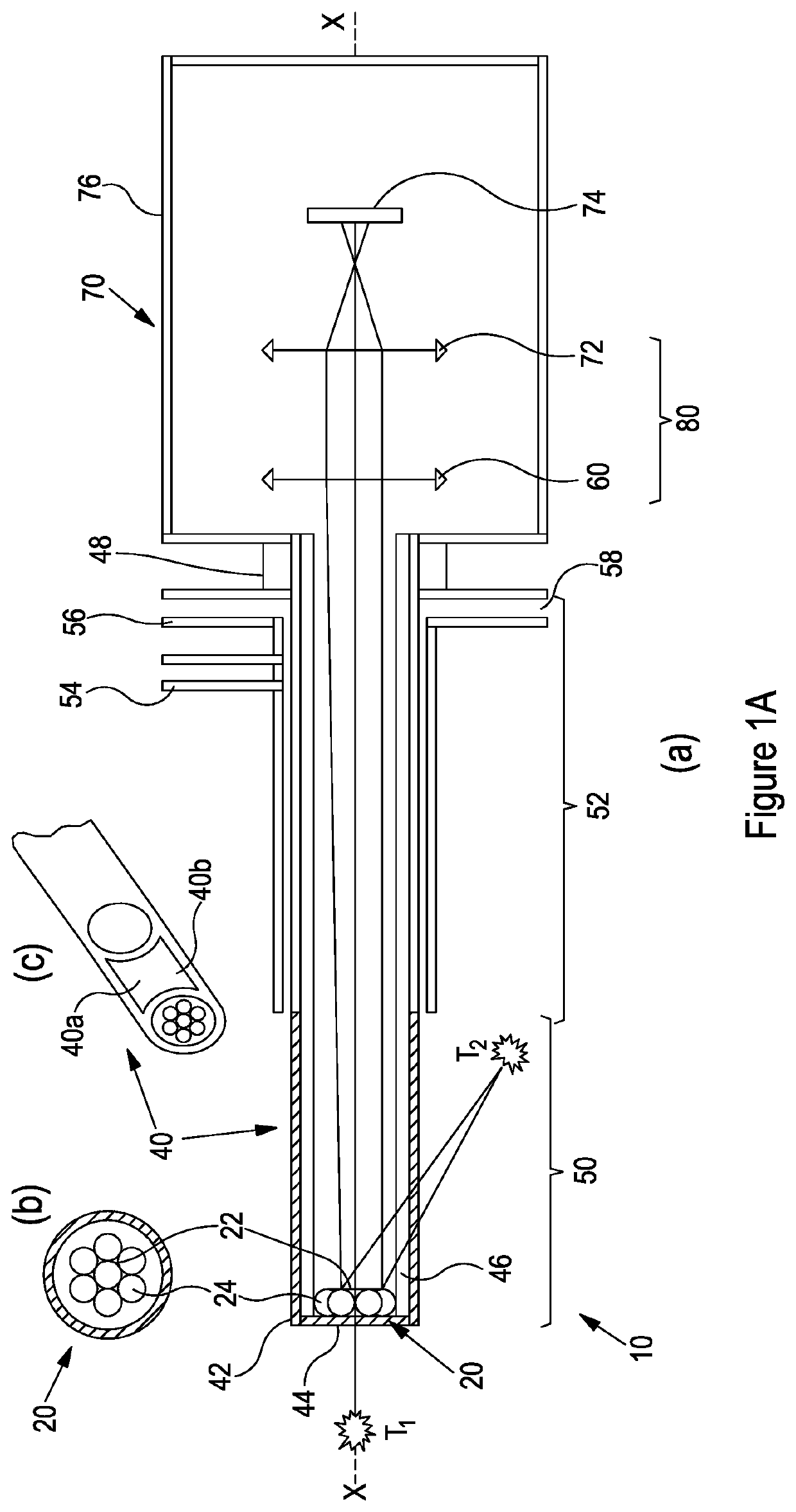
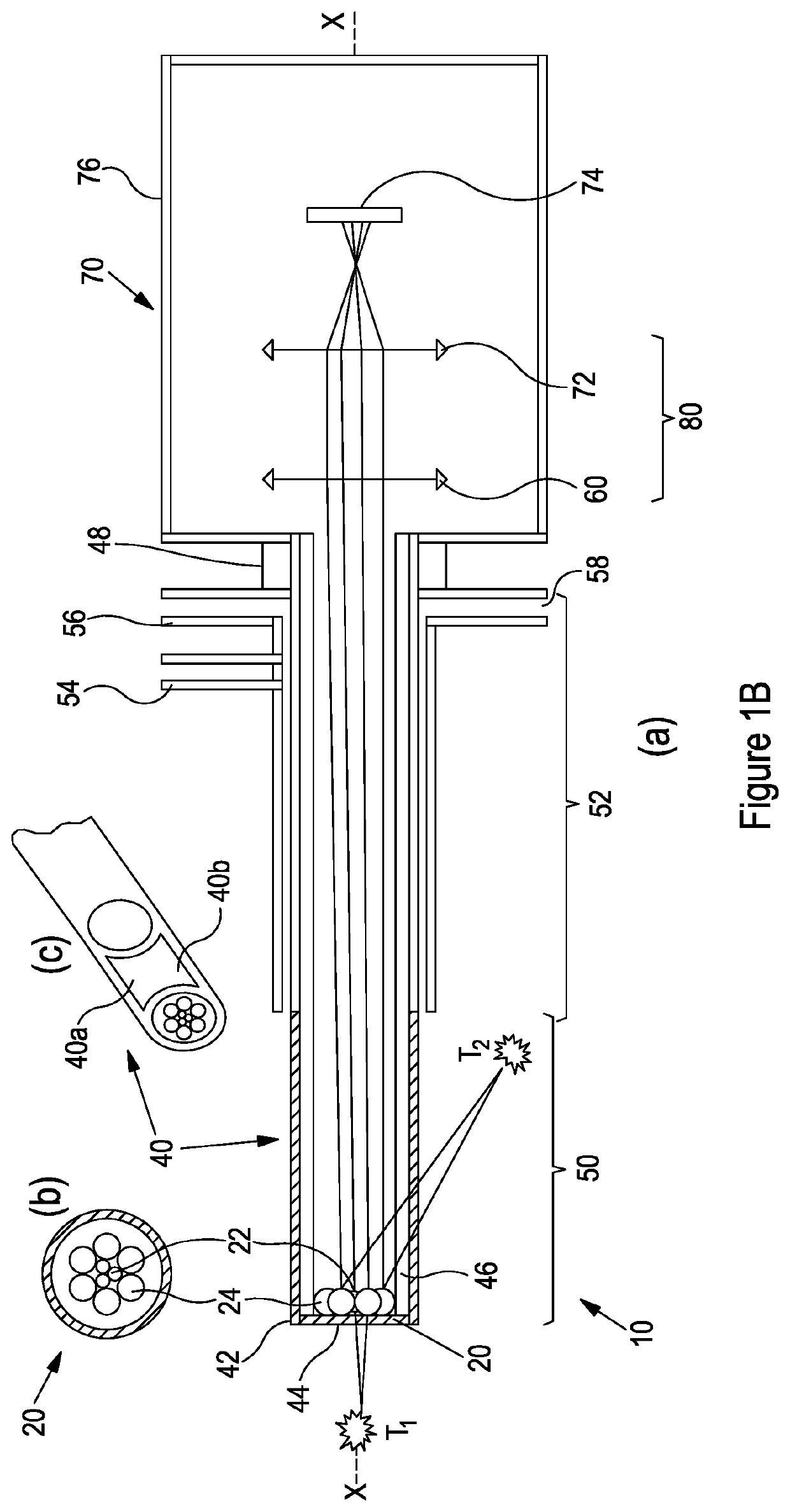
[0072]FIG. 0 shows an imaging system 010. The imaging system 010 comprises a first (distal) optic or set of optics 020. The first set of optics 020 may comprise one or more refractive and / or reflective optical elements. The optics 020 may be supported by a support structure (not shown in FIG. 0; equivalent support structure 21 is shown in FIGS. 3(a)-(l)). The support structure 21 may be transparent at least in part and / or opaque at least in part.

[0073]The optic(s) 020 is (are) housed within a longitudinal enclosure 040 and are aligned along the central longitudinal axis X-X of the enclosure 040. The (radial) plane of the first optic 020 is transverse to the longitudinal axis X-X (the axial direction). The first optic 020 is positioned at or near a first end 042 of the enclosure 040. The first end 042 of the enclosure has a window or opening 044 also aligned transverse to the longitudinal axis X-X. The window 44 could be plain glass or plastic (or other suitable transparent or semi-t...


PUM


Abstract

An imaging device (010, 10, 110) comprises a first optical system (020, 20, 120) at a distal end of the imaging device, a second optical system (080, 80, 180) towards the proximal end of the imaging device, and a sensor (074, 74, 174) at the proximal end of the imaging device. The first and second optical systems and the sensor are aligned along a common longitudinal axis. The first optical system is or comprises one or more reflective and / or refractive optical components (24, 124; 22, 122) symmetrically and / or coaxially arranged with respect to the longitudinal axis, and the second optical system comprises one or more reflective and / or refractive optical components (24, 124; 22, 122) for focussing incident light towards the sensor. A calibration system (200) and method for calibrating such an imaging device, and a method of processing image data obtained from such an imaging device are also provided.

Description

TECHNICAL FIELD[0001]The present invention relates to an imaging system and method and, in particular but not exclusively, to an imaging system and method for generating a 3D representation of an imaged scene. Systems and methods of calibrating and / or processing measured data are also provided.BACKGROUND TO THE INVENTION[0002]Imaging techniques such as endoscopy and borescopy are widely used to obtain information on internal structures e.g. inside a person's body, as a borescope, for architectural or archaeological excavations, safe bomb disposal etc. Typically an endoscope or borescope has a light delivery system to illuminate a target and a lens system for transmitting light from the target to a sensor or camera.[0003]Most endoscopes and borescopes permit light to enter through a transparent window at the front or offset by some angle to the side. Whilst readily available and relatively inexpensive, simple endoscopes or borescopes of this kind run the risk of not seeing a potentia...

Claims


Application Information

Patent Timeline
IPC IPC(8): G02B23/24
CPCG02B23/243A61B1/00163G02B23/2484A61B1/00179A61B1/00193G02B23/2415G02B23/2423A61B1/00057A61B1/00096A61B1/00177A61B1/00181A61B1/00009A61B1/00174G02B13/06G02B23/2407G06T7/73G06T7/80G06T7/97A61B2576/00G06T2200/04G06T2207/10068G06T2207/30032
Inventor MURRAY, NEIL JOHN
Owner 3D OSCOPY LTD
Why Eureka
Try Eureka