
Dynamic information projection for a wall sensor

a wall sensor and dynamic information technology, applied in the direction of signaling systems, electric/magnetic detection for transportation, instruments, etc., can solve the problems of skewed angle of handheld detectors, easy misalignment of lines, and inability to distinguish side edges of lines

Active Publication Date: 2014-05-22
ZIRCON
View PDF12 Cites 4 Cited by
  • Summary
  • Abstract
  • Description
  • Claims
  • Application Information

AI Technical Summary

Benefits of technology

The patent text describes a new invention and its technical effects. The technical effects of the invention will be explained in detail below.

Problems solved by technology

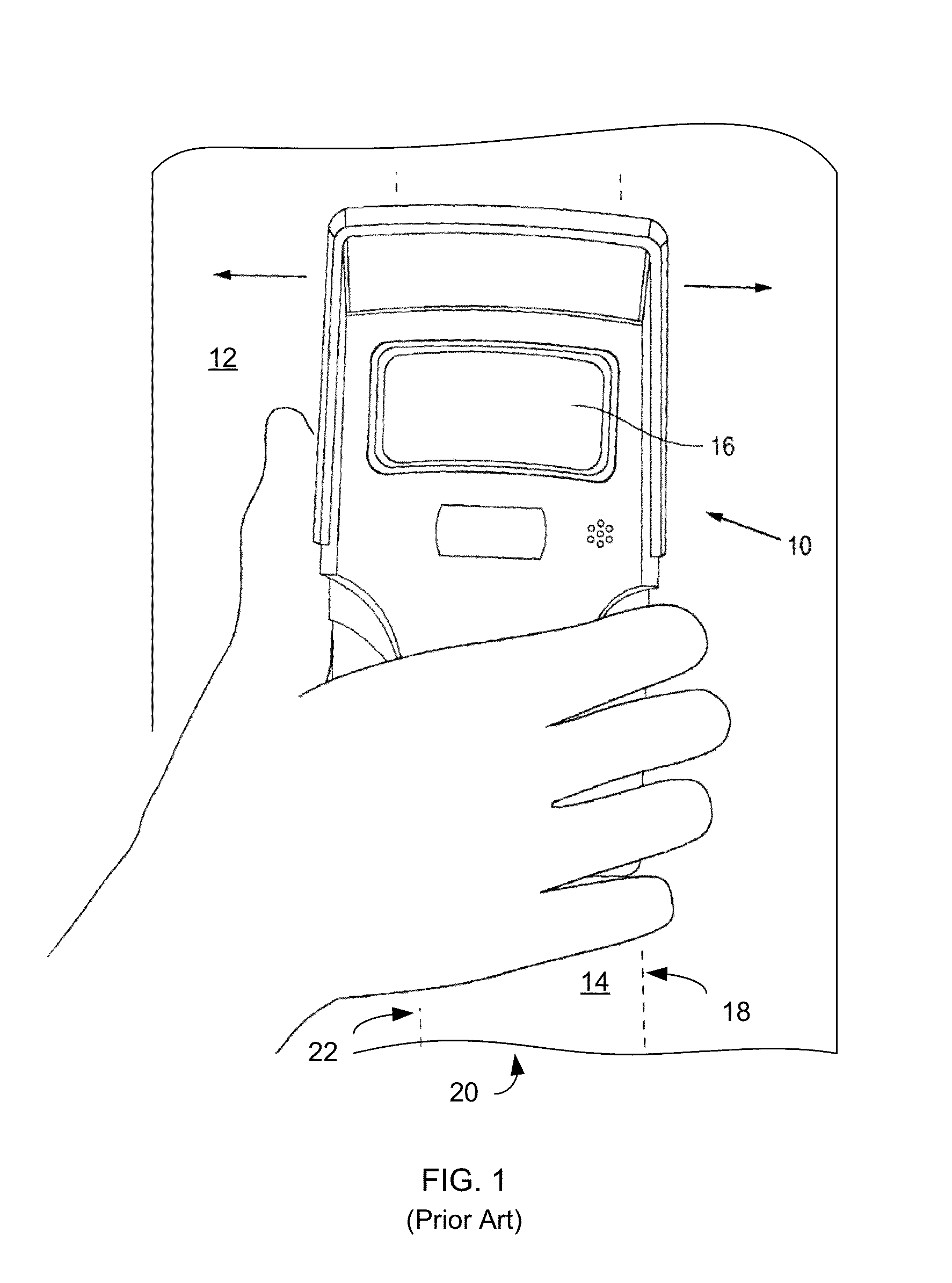
Furthermore, users often operate handheld detectors at skewed angles and in unusual positions such as when searching for objects that are behind ceilings, floors, corners, etc.
Furthermore, the projected line may not have distinct side edges or the line may easily be misaligned due to the LED being butted against the aperture opening.

Method used


Image

  • Dynamic information projection for a wall sensor
  • Dynamic information projection for a wall sensor
  • Dynamic information projection for a wall sensor

Examples


Embodiment Construction

[0028]In the following description, reference is made to the accompanying drawings, which illustrate several embodiments of the present invention. It is understood that other embodiments may be utilized and mechanical, compositional, structural, electrical, and operational changes may be made without departing from the spirit and scope of the present disclosure. The following detailed description is not to be taken in a limiting sense. Furthermore, some portions of the detailed description that follows are presented in terms of procedures, steps, logic blocks, processing, and other symbolic representations of operations on data bits that can be performed in electronic circuitry or on computer memory. A procedure, computer executed step, logic block, process, etc., are here conceived to be a self-consistent sequence of steps or instructions leading to a desired result. The steps are those utilizing physical manipulations of physical quantities. These quantities can take the form of e...


PUM


Abstract

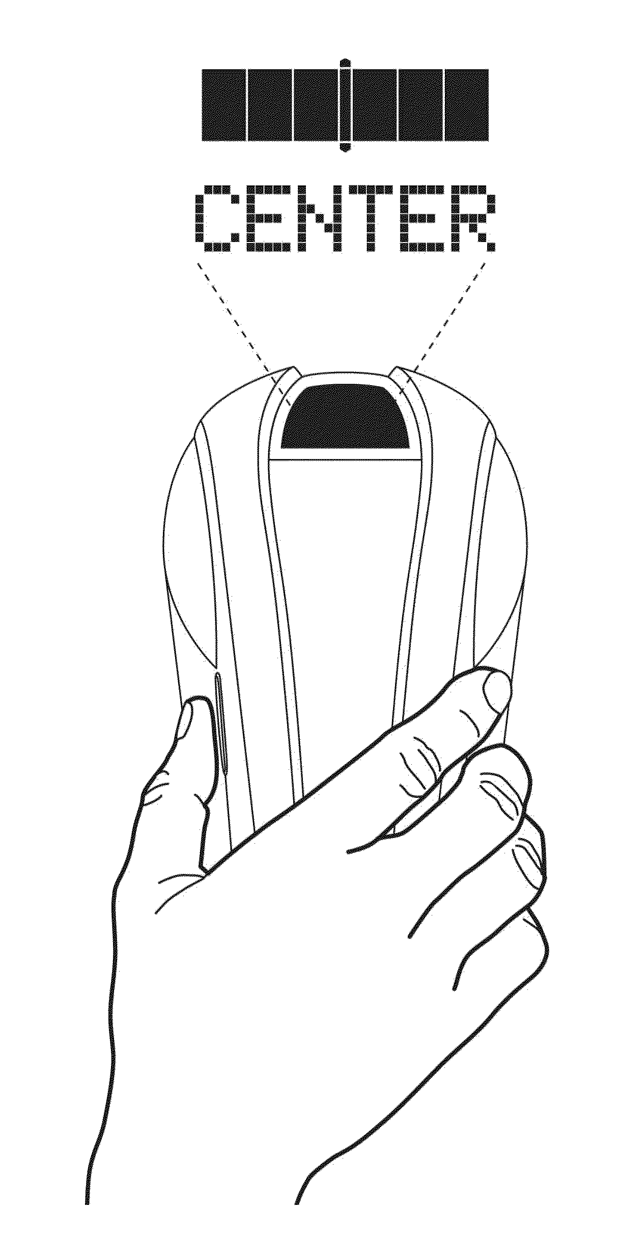
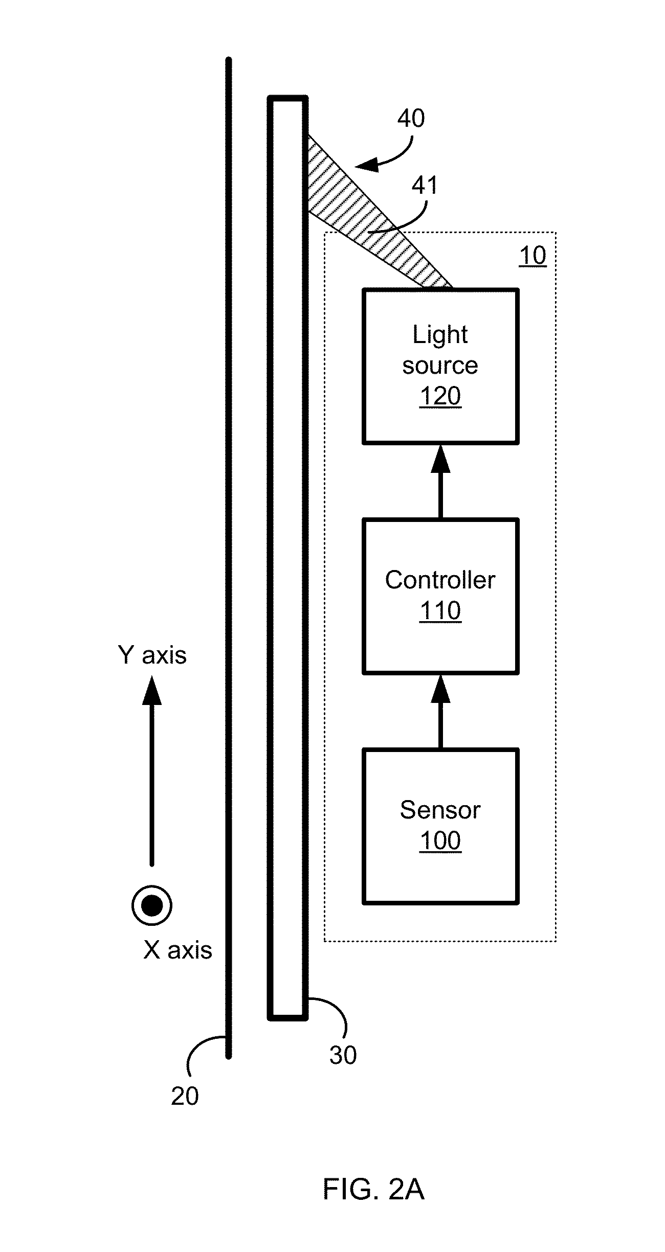
An implementation of a system, device and method for projecting a visual indicator against a surface is provided. A display projection system in a handheld sensor device (e.g. a handheld wall scanner) projects a static or computer-controlled dynamic pattern of light onto a surface being scanned to indicate a specific feature, such as existence of solid structures of wood, metal or plastic, electric or magnetic fields, or a disturbance of a field. The projected light may be controlled by a computer via an aperture to allow flexibility in what is projected, such as icons, lines, graphics, characters and colors.

Description

CROSS-REFERENCE TO RELATED APPLICATIONS[0001]This application is a continuation and claims the benefit under 35 U.S.C. §120 of U.S. application Ser. No. 12 / 580,894 by Barry Wingate as the first named inventor, entitled “Dynamic information projection for a wall sensor”, and filed Oct. 16, 2009, which is incorporated herein by reference in its entirety, which claims the benefit under 35 U.S.C. §119(e) of U.S. Provisional Application Ser. No. 61 / 105,856 by Anthony J. Rossetti as the first named inventor, entitled “Dynamic information projection for a wall sensor”, and filed Oct. 16, 2008, which is incorporated herein by reference in its entirety.BACKGROUND OF THE INVENTION[0002]1. Field of the Invention[0003]The invention relates generally to handheld sensor devices, such as stud sensors, and more specifically to projection of visual indicators against a surface regarding a hidden object.[0004]2. Background of the Invention[0005]Portable sensors, including handheld detector units, are...

Claims


Application Information

Patent Timeline
Patent Type & Authority Applications(United States)
IPC IPC(8): G08B5/36
CPCG01V3/15G08B5/36
Inventor WINGATE, BARRYROSSETTI, ANTHONY J.KRANTZ, NORMAN LAVARSTAUSS, JOHN R.
Owner ZIRCON
Learn More