Virtual image display apparatus
a virtual image and display apparatus technology, applied in the field of virtual image display apparatus, can solve the problems of reducing reducing the resolution of the image generator, so as to reduce the amount of trapezoidal correction and reduce the amount of unused. , the effect of reducing waste and increasing the video image area
- Summary
- Abstract
- Description
- Claims
- Application Information
AI Technical Summary
Benefits of technology
Problems solved by technology
Method used
Image

Examples
first embodiment
[0036]A virtual image display apparatus according to a first embodiment of the invention will be described below in detail with reference to the drawings.
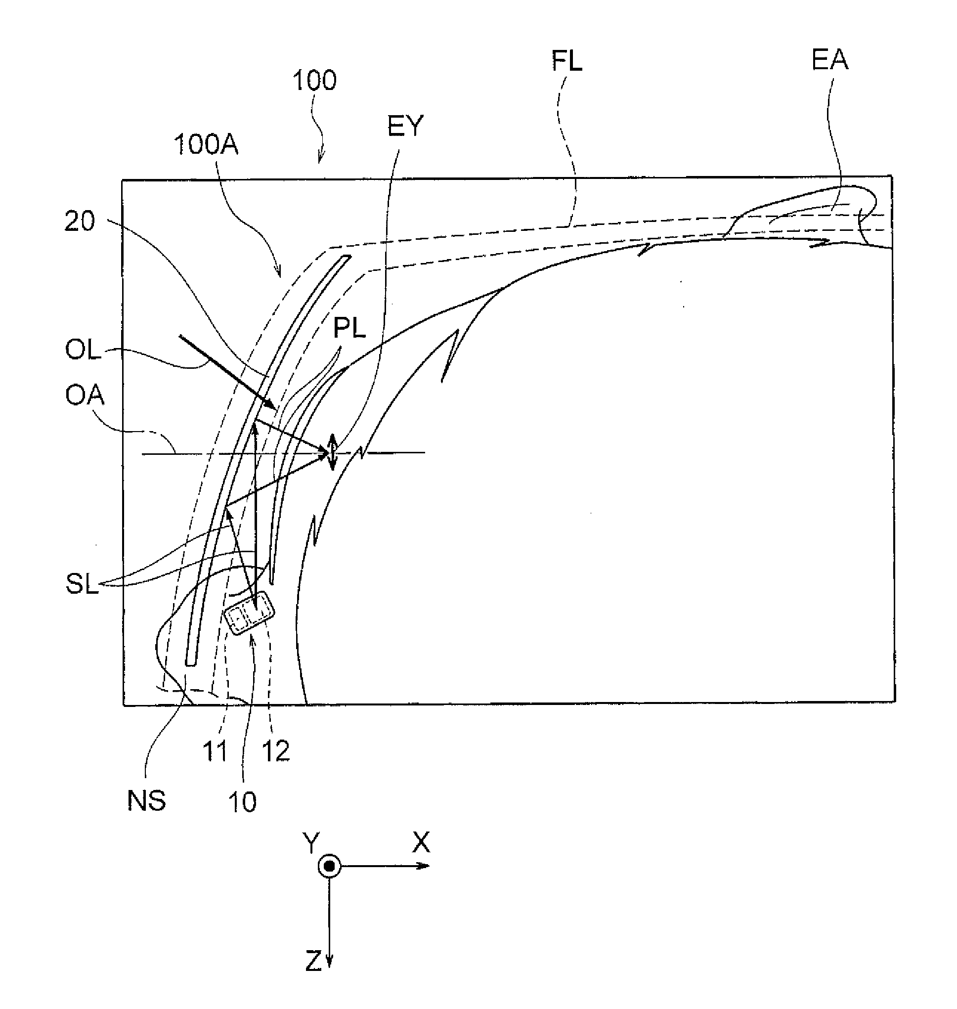
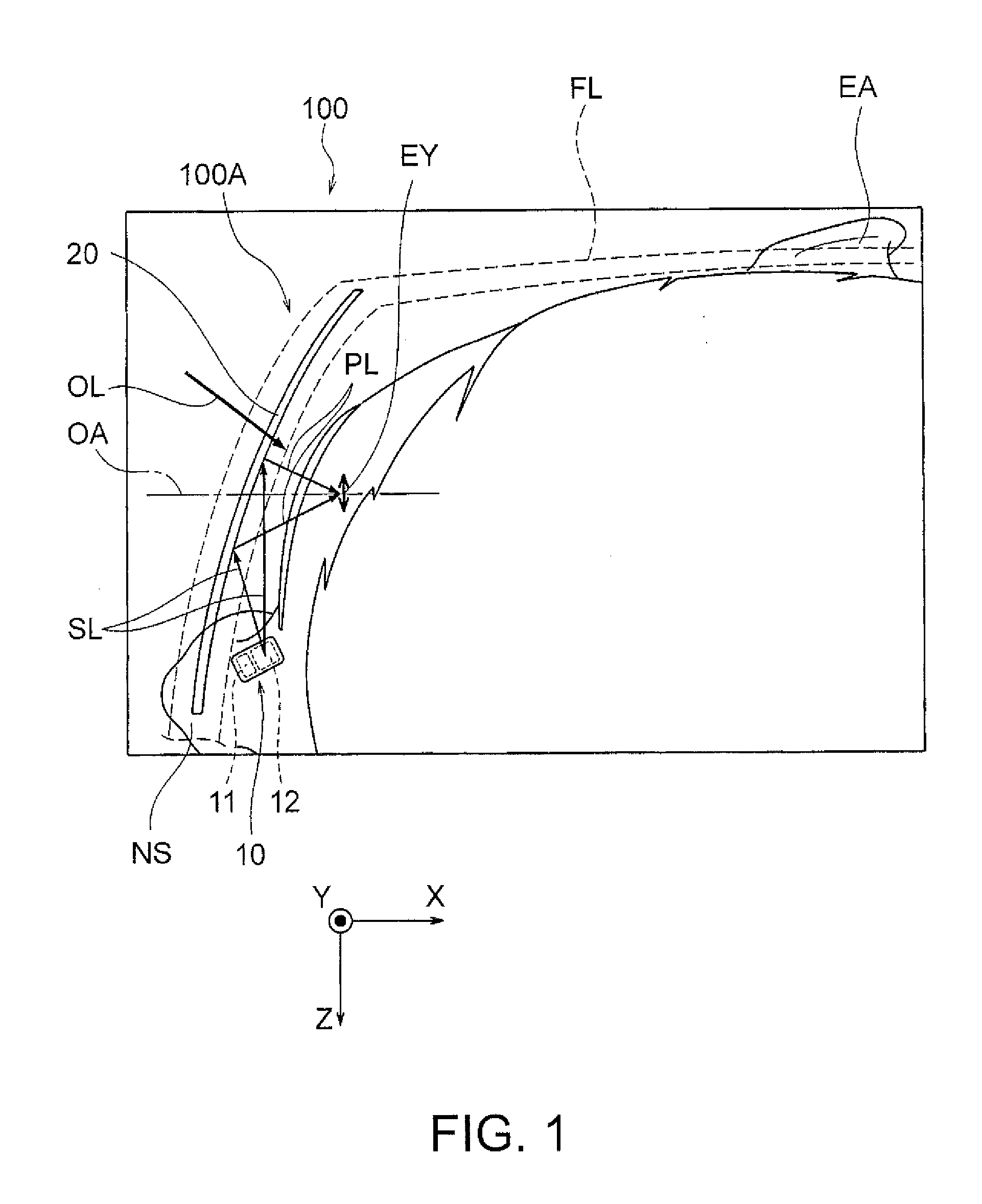
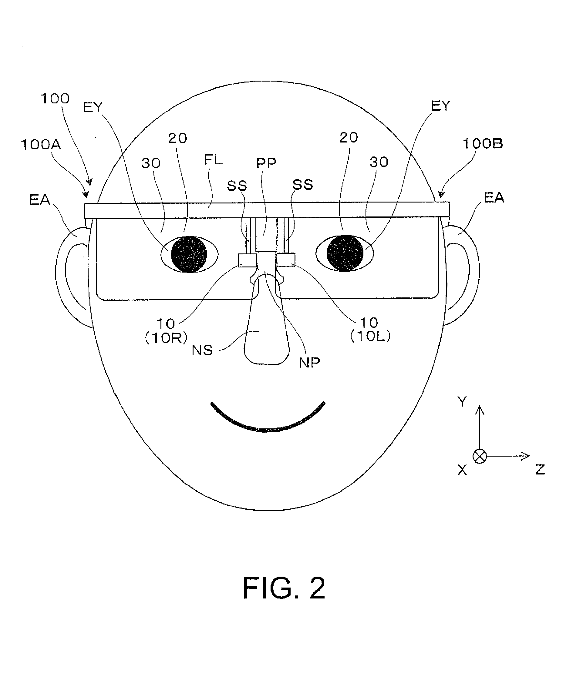
[0037]A virtual image display apparatus 100 according to the embodiment shown in FIG. 1, which is a head-mounted display having a spectacle-like external appearance, not only allows a wearer (user), a viewer who wears the virtual image display apparatus 100, to recognize image light corresponding to a virtual image but also allows the wearer, the user of the virtual image display apparatus 100, to view an image formed by outside light in see-through observation. FIG. 1 is a partial enlarged view showing a state in which the wearer wears the virtual image display apparatus 100, and part of the virtual image display apparatus 100 is omitted. Specifically, a first display unit 100A is part of the virtual image display apparatus 100 and forms a virtual image on the right-eye side. In the virtual image display apparatus 100, the first d...
second embodiment
[0090]A virtual image display apparatus according to a second embodiment will be described below. The virtual image display apparatus according to the present embodiment is a variation of the virtual image display apparatus 100 according to the first embodiment and is the same as the virtual image display apparatus 100 according to the first embodiment unless otherwise specified. Further, the right-eye side and the left-eye side are the same but only reversed. Therefore, only the right-eye side will be described and no description of the left-eye side will be made. In the present embodiment as well, the first display unit functions by itself as a virtual image display apparatus.
[0091]In the virtual image display apparatus according to the present embodiment, the video image area RR is divided into three areas, a first video image area RR1, a second video image area RR2, and a third video image area RR3, as shown in FIG. 9. In this case, the third video image area RR3 can display vid...
third embodiment
[0092]A virtual image display apparatus according to a third embodiment will be described below. The virtual image display apparatus according to the present embodiment is a variation of the virtual image display apparatus 100 according to the first embodiment and is the same as the virtual image display apparatus 100 according to the first embodiment unless otherwise specified.
[0093]FIG. 10 is a plan view of the virtual image display apparatus according to the present embodiment. As shown in FIG. 10, a first display unit 200A of a virtual image display apparatus 200 according to the present embodiment includes a light output section 10 including a video image generation section, a light guide member 220, which is a virtual image formation section, and a light transmissive member 250. The light guide member 220 and the light transmissive member 250, each of which is a light transmissive prism member, are bonded to and integrated with each other. The virtual image display apparatus 2...
PUM
 Abstract
Description
Claims
Application Information
 - R&D
- Intellectual Property
- Life Sciences
- Materials
- Tech Scout
- Unparalleled Data Quality
- Higher Quality Content
- 60% Fewer Hallucinations
Browse by: Latest US Patents, China's latest patents, Technical Efficacy Thesaurus, Application Domain, Technology Topic, Popular Technical Reports.
© 2025 PatSnap. All rights reserved.Legal|Privacy policy|Modern Slavery Act Transparency Statement|Sitemap|About US| Contact US: help@patsnap.com