Rotary mechanism with articulating rotor

a rotary mechanism and rotating rotor technology, applied in the direction of rotary piston engines, rotary or oscillating piston engines, liquid fuel engines, etc., can solve the problem of difficult to meet the desired fuel economy of such engines that must operate at relatively high rotational speeds

Inactive Publication Date: 2014-05-22
KUWAIT UNIV
View PDF8 Cites 8 Cited by
  • Summary
  • Abstract
  • Description
  • Claims
  • Application Information

AI Technical Summary

Benefits of technology

[0010]These and other features of the present invention will become readil

Problems solved by technology

Appropriate external gear reduction is easily incorporated to reduce the RPM to the desired rotational speed at the driveshaft and wheels of a motor

Method used


Image

  • Rotary mechanism with articulating rotor
  • Rotary mechanism with articulating rotor
  • Rotary mechanism with articulating rotor

Examples


Embodiment Construction

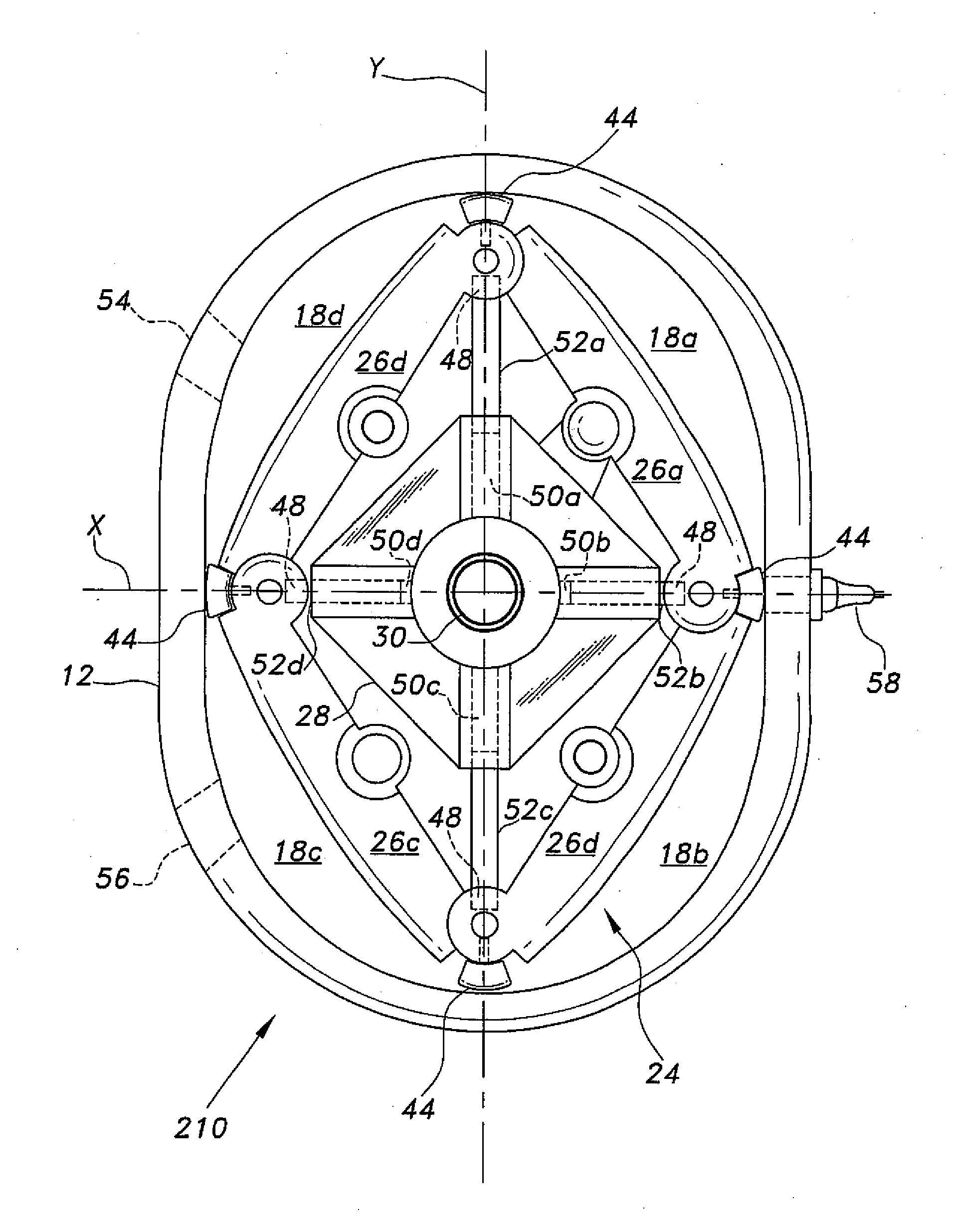
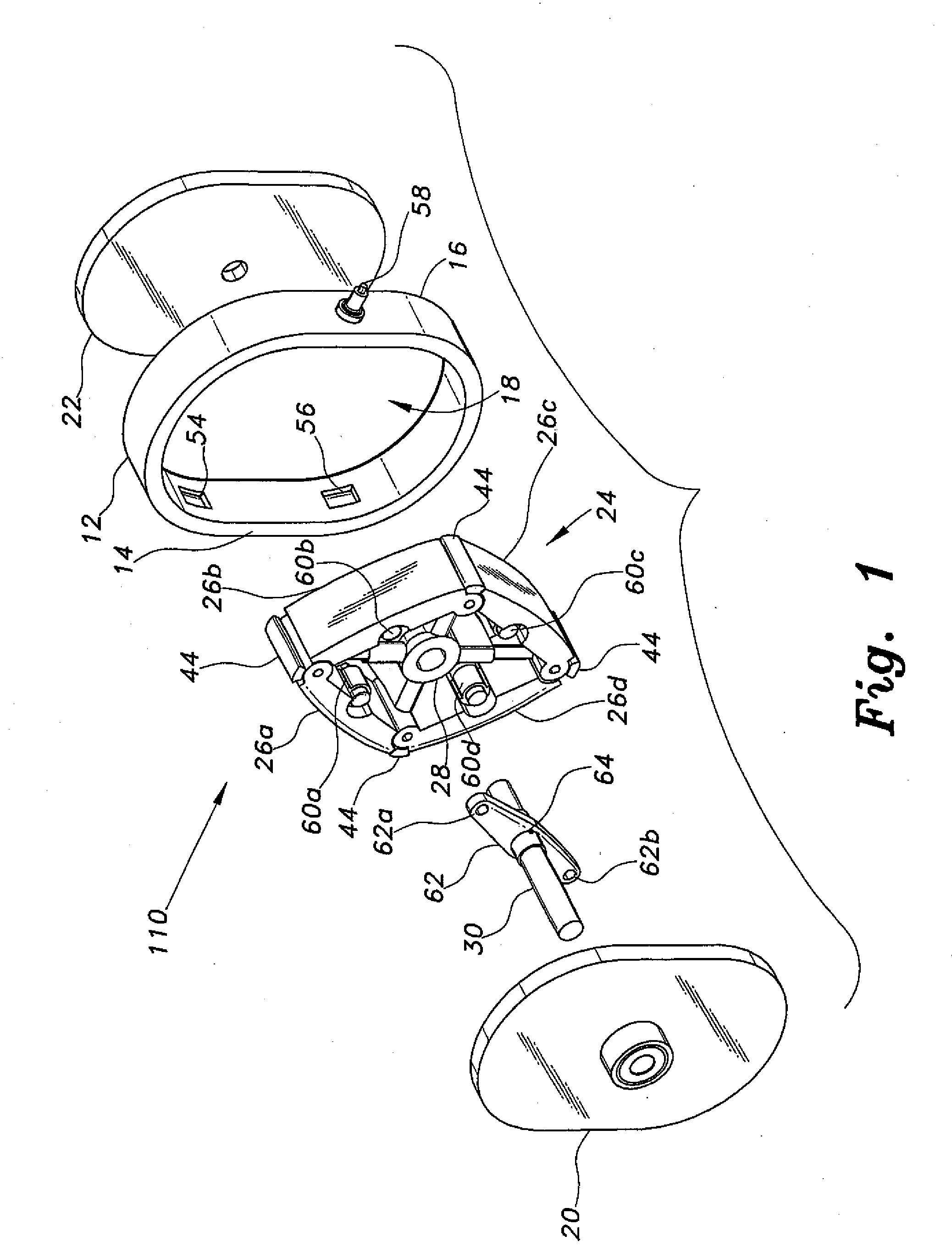
[0028]The rotary mechanism with articulating rotor comprises a stationary case or housing having a non-circular chamber, and an internal rotor comprising four segments pivotally attached to one another at their ends. The articulating rotor segments define varying volumes in portions of the non-circular chamber as the rotor revolves within the chamber. The mechanism may be configured as a power output device (e.g., internal combustion engine, or hydraulically or pneumatically powered motor or compressor), or to receive power from an external source to serve as a hydraulic or pneumatic pump or compressor.

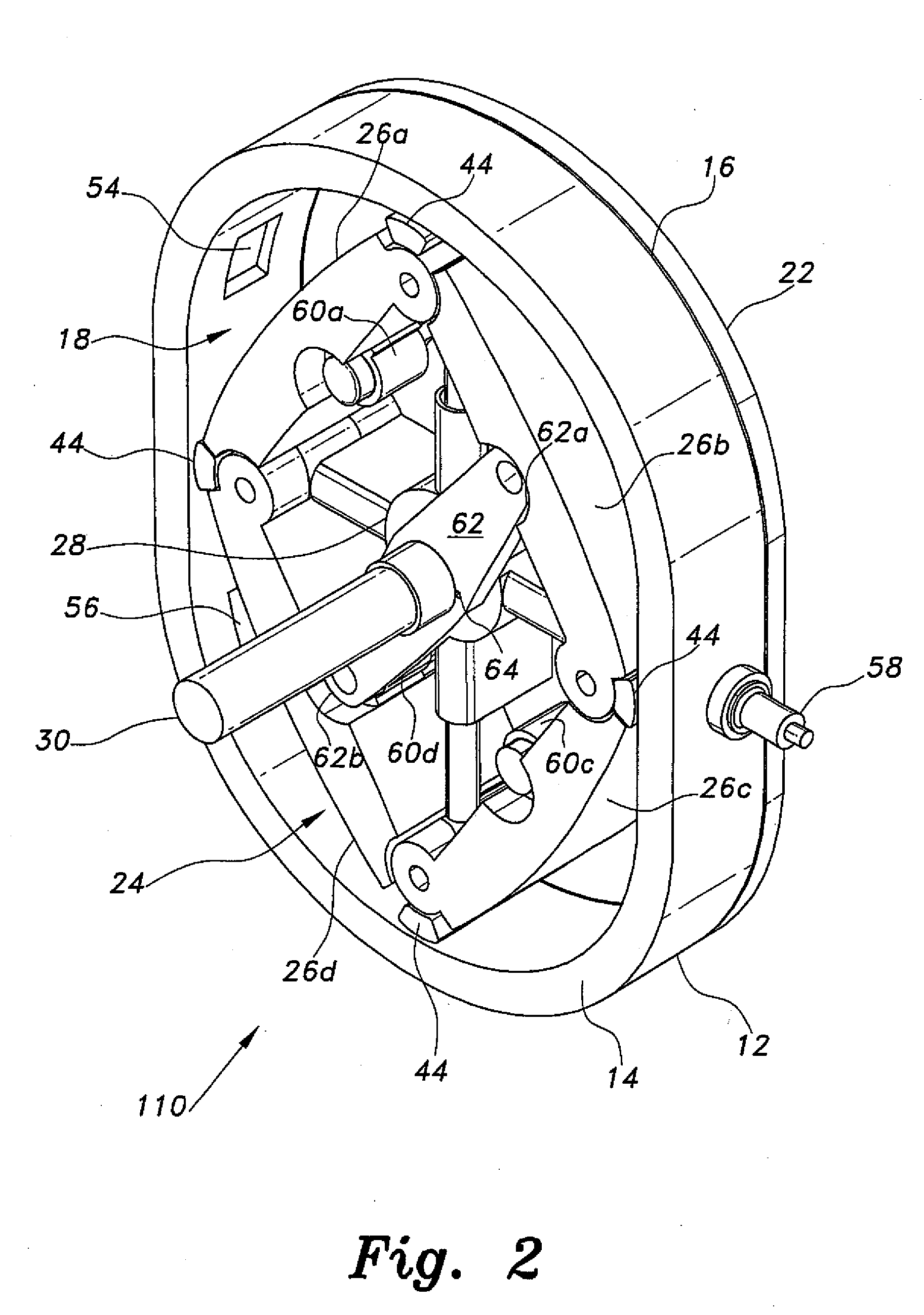
[0029]FIG. 1 of the drawings provides an exploded perspective view of a first embodiment 110 of the rotary mechanism. FIG. 2 illustrates the assembled mechanism 110 with its forward or first end plate removed to show the rotor installed therein. The rotary mechanism 110 includes a case or housing 12 having a first end 14, an opposite second end 16, and an epitrochoidal chamber 18 ther...


PUM


Abstract

The rotary mechanism with articulating rotor may be adapted as a pump or compressor when external power is applied to its shaft, as a motor when differential pressure is applied to its inlet and outlet ports, or as an internal combustion engine when provided with fuel, air, and ignition source. The mechanism includes an internal chamber having major and minor diameters. An articulating rotor having four linked segments rotates therein. The segments allow the rotor to articulate between square and rhomboid shapes as it rotates within the chamber, the rotor segments forming variable volume chamber portions as they rotate. The rotor segments are linked to the central shaft either by a transverse arm rotationally affixed to the central shaft and to diametrically opposed rotor segments, or by telescoping rods connecting the linked ends of the rotor segments to the central shaft.

Description

BACKGROUND OF THE INVENTION[0001]1. Field of the Invention[0002]The present invention relates generally to pumps, compressors, motors, and internal combustion engines, and particularly to a rotary mechanism having a multiple-segment articulating rotor for defining a plurality of internal chamber volume portions and for varying the volume portions during operation.[0003]2. Description of the Related Art[0004]Rotary mechanisms, i.e., pumps, motors, and internal combustion engines, have been known for a considerable period of time. Perhaps the most widely used application of such devices is in the field of hydraulic pumps and motors. The Wankel engine incorporating a two-lobe, epitrochoidal chamber and a triangular rotor has also found some application as a powerplant in various automobiles and motorcycles.[0005]One characteristic of this configuration, particularly in internal combustion engines, is that the rotary speed must be relatively high in order to produce power. The single ro...

Claims


Application Information

Patent Timeline
IPC IPC(8): F01C1/44F02B55/14F04C2/44
CPCF01C1/22F01C21/08F02B55/14Y02T10/12F04C2/44F01C1/44
Inventor AL-HAWAJ, OSAMAH M.
Owner KUWAIT UNIV
Why Eureka
Try Eureka