Electronic Caliper Configured to Generate Power for Measurement Operations

a technology of electronic calipers and power supply, applied in the field of electronic calipers, can solve the problems of battery replacement periodically, unwanted inconvenience and/or expense for users,

Active Publication Date: 2014-06-05
MITUTOYO CORP
View PDF7 Cites 16 Cited by
  • Summary
  • Abstract
  • Description
  • Claims
  • Application Information

AI Technical Summary

Benefits of technology

[0005]When generating power to eliminate or postpone the need for battery replacement in a caliper, it would be desirable and most convenient if power generation in the caliper results from ergonomic and convenient motions over a relatively short range of motion.

Problems solved by technology

Nonetheless, even in low power configurations, batteries need replacement periodically.
This is seen by some users as an unwanted inconvenience and / or expense.

Method used


Image

  • Electronic Caliper Configured to Generate Power for Measurement Operations
  • Electronic Caliper Configured to Generate Power for Measurement Operations
  • Electronic Caliper Configured to Generate Power for Measurement Operations

Examples


first embodiment

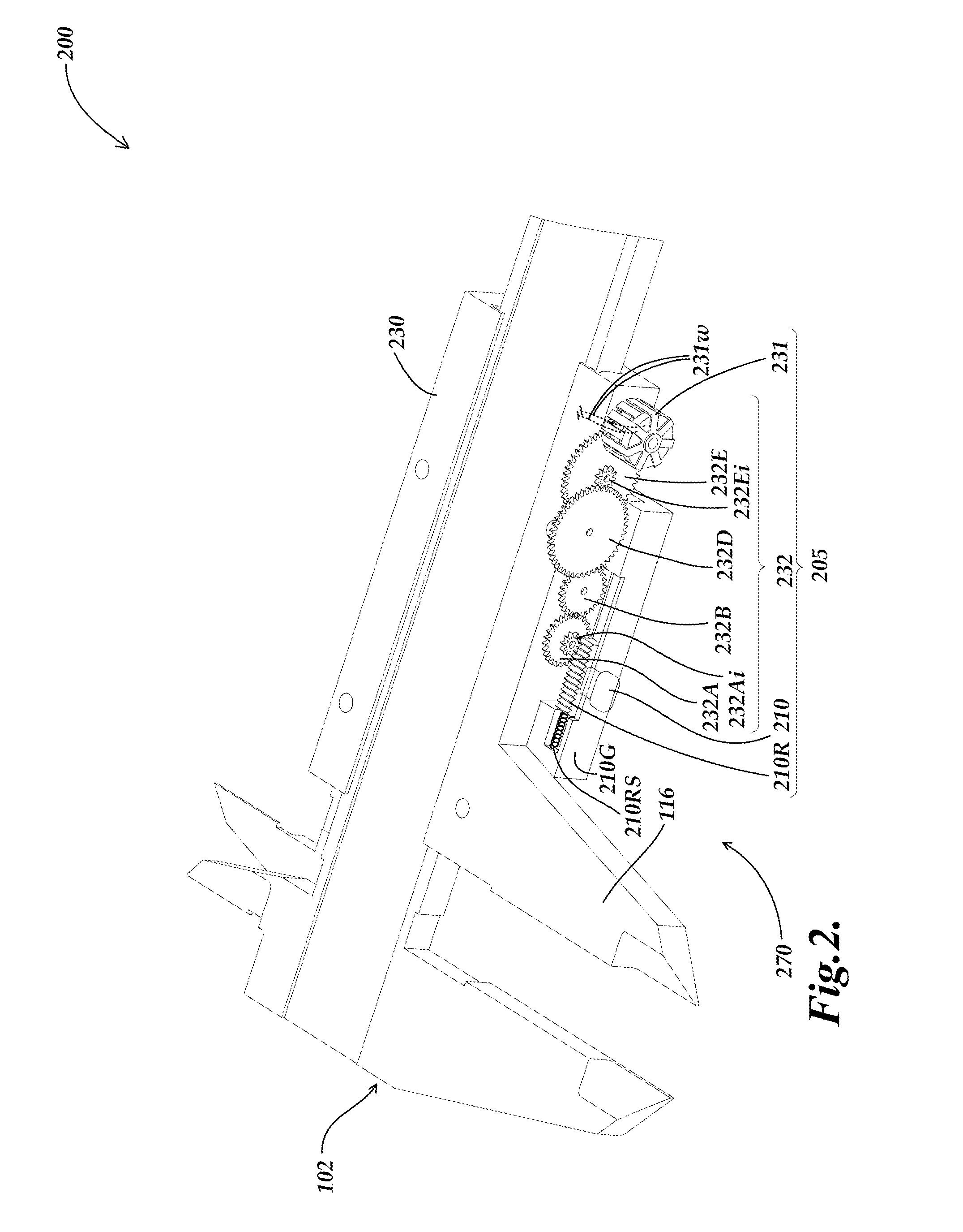
[0036]FIG. 2 is a diagram of a power generating arrangement 205 integrated in a caliper 200. The caliper 200 may be similar to the caliper 100, and therefore only the significant differences are described with respect to FIG. 2. Certain portions of the scale member 202 are omitted from FIG. 2, such that various components of the power generating arrangement 205 may be more clearly illustrated. As illustrated in FIG. 2, the power generating arrangement 205 is integrated with and moves with the slider 230 (which may be used in the slider assembly 170, shown in FIG. 1). The power generating arrangement 205 comprises a gear assembly 232 and a power generator 231 and a power generating handle 210. In this embodiment, the power generating handle 210 is connected to a rack 210R including gear teeth. The power generating handle 210 is driven by a user (e.g., by the user's right hand thumb, while the slider is held in the user's other right hand fingers) which drives the rack 210R. The power...

second embodiment

[0048]FIGS. 4A and 4B are detailed diagrams of a portion of a gear assembly 432 which may be incorporated in a power generating arrangement 405 which is integrated in a caliper according to the principles disclosed herein. FIG. 4C shows additional details of one embodiment of a power generator 431 as integrated into a caliper. The gear assembly 432 may be similar to the gear assembly 232 and elements numbered 4XX may be similar or analogous to elements 2XX of the caliper 200. Therefore, only the significant differences are described in detail with respect to FIGS. 4A and 4B. The gear assembly 432 is different than the gear assembly 232 in that it includes a force-limiting clutch 432C, which is shown in FIG. 4A and further magnified in FIG. 4B, described further below.

[0049]As previously indicated, it is desirable that when the power generating arrangement 405 generates power as the user moves the power generating handle 410, it contributes a motion resistance force component of at m...

third embodiment

[0057]FIGS. 5A and 5B are diagrams illustrating a portion of a power generating arrangement 505 integrated in a caliper 500. The caliper 500 may be similar to the caliper 200, the power generating arrangement 505 may be similar to the power generating arrangement 205 or 405, and elements numbered 4XX may be similar or analogous to elements 2XX of the caliper 200 or elements 4XX of the caliper power generating arrangement 405. Therefore, only the significant differences are described in detail with respect to FIGS. 5A and 5B.

[0058]In particular, the gear assembly 532 is different than the gear assemblies 232 and 432 in that the input element that provides the function of the previously described input gear (e.g., the gear 232Ai or 432Ai) is a friction roller 532Ai that may be joined to an outer gear 532A. The friction roller 432Ai engages, through friction, at least one edge of a surface block 510SB connected to the power generating handle 510, and is thereby rotated to drive the out...


PUM


Abstract

An electronic caliper generates power for measurement operations. The caliper comprises a scale member, a slider, a signal processing portion configured to measure a displacement between the scale member and slider, a power generating arrangement attached to the slider comprising a gear assembly configured to rotate in response to a force provided through a power generating handle to the gear assembly by a user moving the power generating handle relative to the gear assembly, and a power generator coupled to the gear assembly and configured to rotate in response to force provided by the rotating gear assembly and provide power to the signal processing portion. The power generating arrangement generates power as the user moves the power generating handle, and the power generating arrangement contributes a motion resistance force component of at most 20N as the user moves the power generating handle with a maximum manual acceleration.

Description

FIELD[0001]The present application relates generally to metrology systems, and more particularly to an electronic caliper that is capable of generating power.BACKGROUND[0002]Various electronic calipers are known that use electronic position encoders. These encoders are generally based on low-power inductive, capacitive, or magnetic position sensing technology. In general, an encoder may comprise a readhead and a scale. The readhead may generally comprise a readhead sensor and readhead electronics. The readhead outputs signals that vary as a function of the position of the readhead sensor relative to the scale, along a measuring axis. In an electronic caliper, the scale is generally affixed to an elongated scale member that includes a first measuring jaw and the readhead is affixed to a slider which is movable along the scale member and which includes a second measuring jaw. Thus, measurements of the distance between the two measuring jaws may be determined based on the signals from ...

Claims


Application Information

Patent Timeline
Patent Type & Authority Applications(United States)
IPC IPC(8): G01B3/30
CPCG01B3/30G01B3/205G01B3/20G01B3/18G01B7/02
Inventor EMTMAN, CASEYNAHUM, MICHAEL
Owner MITUTOYO CORP
Why Eureka
Try Eureka