
Tool holder for an aerial bucket lift

a bucket lift and tool holder technology, applied in the field of tool holders, can solve the problems of inconvenient and safe place, complicated and dangerous jobs, and achieve the effect of resisting chipping and cracking

Active Publication Date: 2014-06-05
SAFE TREE PROD
View PDF13 Cites 7 Cited by
  • Summary
  • Abstract
  • Description
  • Claims
  • Application Information

AI Technical Summary

Benefits of technology

The present invention provides a tool holder that can be hung on an aerial bucket lift, securely holding the tool. The holder is made from a strong plastic that resists damage. This solves the problem of previous tool holders being easily damaged while in use.

Problems solved by technology

Tradesmen that cut and trim tree branches from a bucket of an aerial bucket lift have dangerous jobs that are complicated by the fact that they are often wielding sharp tools such as chainsaws and hand saws.
The small confines of the bucket also provides the additional complication of not providing a convenient and safe place to temporarily hold a chainsaw or hand saw if the tradesman needs to use both hands.
Although there are prior art holders for chainsaws and handsaws, these prior art devices are often made or lightweight plastic or fiberglass, which is prone to chipping and cracking.
Consequently, tradesmen often rip pants and cut their legs on jagged holders or the sharp blades of their tools.

Method used


Image

  • Tool holder for an aerial bucket lift
  • Tool holder for an aerial bucket lift
  • Tool holder for an aerial bucket lift

Examples


first embodiment

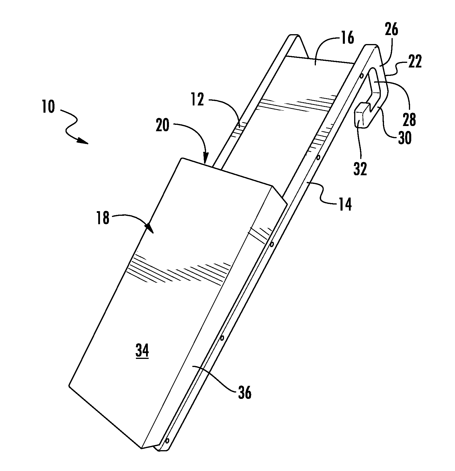
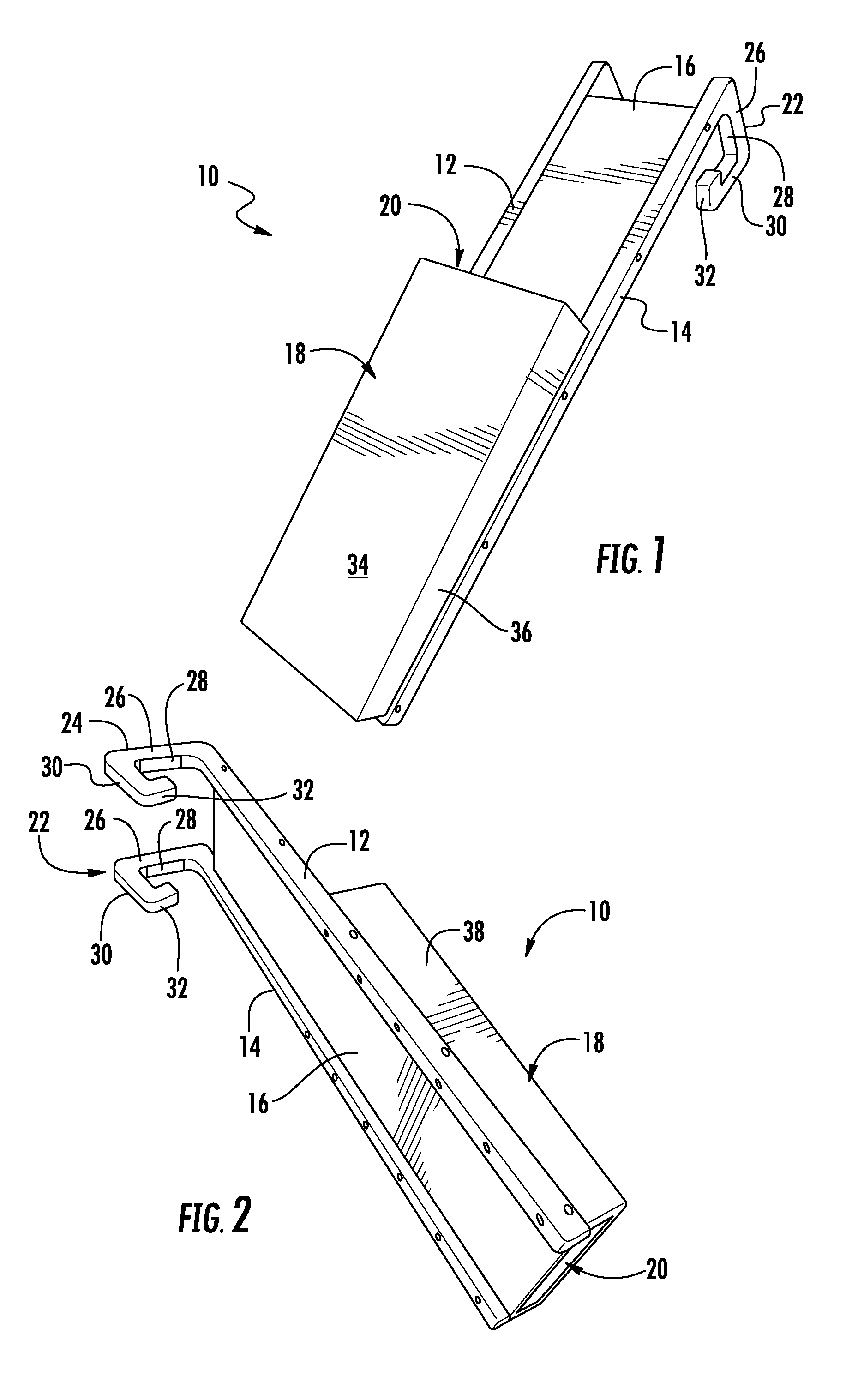
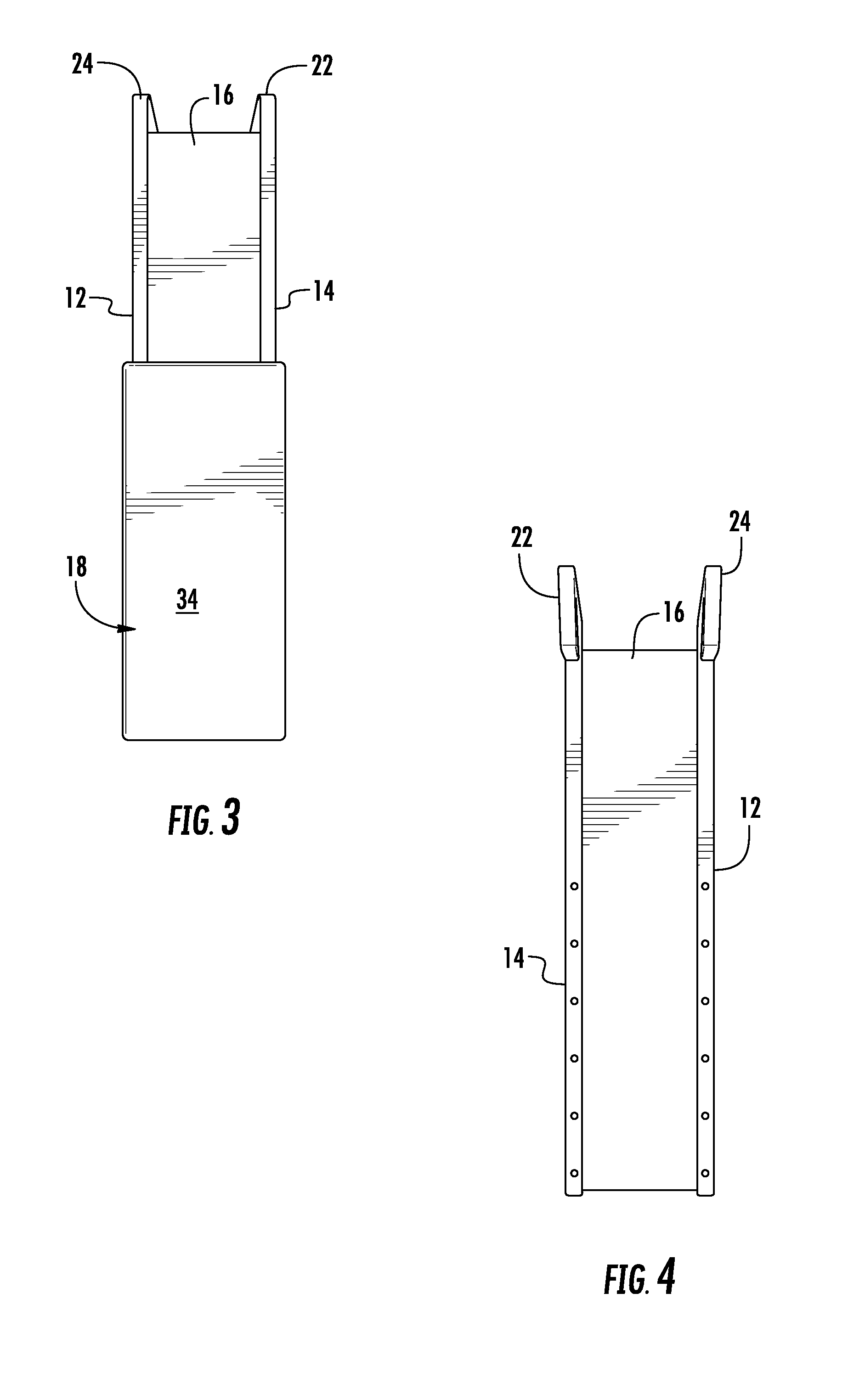
[0037]Referring to FIGS. 1-7, a tool holder adapted as a chainsaw scabbard is shown generally at 10. The chainsaw scabbard 10 has a left side member 12 and a right side member 14 fastened to a backboard 16. A scabbard portion 18 is fastened to the left side member 12 and the right side member 14 forming a pocket 20 to hold a blade of a chainsaw.

[0038]Extending from the left side member 12 and the right side member 14 are a left hook 22 and a right hook 24, respectively. The left hook 22 and right hook 24 each include a top portion 26 extending laterally and rearwards from the respective left side or right side members 12, 14. Underneath the top portion 26, padded or rubberized tape 28 may be added to prevent lateral slipping and sliding on the bucket 99.

[0039]Depending downwards from the top portion 26 is a back support portion 30 with a foot 32 extending inwardly therefrom, or rather, back towards the left or right side portion 12, 14, respectively. The foot portion 32 provides bra...

embodiment 600

[0050]Referring to FIGS. 21-24, another alternative embodiment 600 is shown of a tool holder adapted as a chainsaw scabbard, which eliminates the chances of the chainsaw blade from impacting a fastener, thereby reducing the likelihood of damage to the chainsaw. Because the tool holder 600 is made from a softer material than a chainsaw blade, such as a high density plastic, the tool holder 600 will wear over time as the blades contact the interior of the scabbard portion 18. In particular, the sides 36, 38 of the scabbard portion 18 are prone to wear early, exposing rear-to-front fasteners that secure the scabbard portion 18 to the side members 36, 38. The fasteners are often made of metal, which can dull or even break the blades on the chainsaw.

[0051]In this alternative embodiment 600 the left and right side members 12, 14 have a hogged out portion 650 sized to cup an edge of the scabbard portion 18. Fasteners are driven laterally through the side members 12, 14, through the scabbar...


PUM


Abstract

A tool holder for a bucket lift is disclosed. The tool holder includes a backboard having left, right, front and back sides. A left side member and a right side member are attached to the left side and right side, respectively, of the backboard. A scabbard portion is attached to the front side of the backboard; the scabbard portion forms a pocket between the scabbard portion and backboard. A left hook and a right hook extend from the left side member and right side member respectively, the left hook and right hook are configured and arranged to couple to a bucket of an aerial bucket lift.

Description

CROSS-REFERENCE TO RELATED APPLICATIONS[0001]This patent document claims priority to earlier filed U.S. Provisional Patent Application Ser. No. 61 / 732,595, filed Dec. 3, 2012, and U.S. Provisional Patent Application Ser. No. 61 / 749,523, filed Jan. 7, 2013, the entire contents of which are incorporated by reference.BACKGROUND[0002]1. Technical Field[0003]The present patent document relates generally to tool holders, and more specifically to tool holders for use in aerial bucket lifts.[0004]2. Background of the Related Art[0005]Tradesmen that cut and trim tree branches from a bucket of an aerial bucket lift have dangerous jobs that are complicated by the fact that they are often wielding sharp tools such as chainsaws and hand saws. The small confines of the bucket also provides the additional complication of not providing a convenient and safe place to temporarily hold a chainsaw or hand saw if the tradesman needs to use both hands. Although there are prior art holders for chainsaws a...

Claims


Application Information

Patent Timeline
IPC IPC(8): B66F13/00
CPCB66F13/00B66F11/04B25H3/00
Inventor REEVES, ALBERT W.
Owner SAFE TREE PROD
Learn More