Power supply apparatus for LED lighting and LED lighting apparatus using the power supply apparatus

a technology of power supply apparatus and led lighting, which is applied in the direction of energy-efficient lighting, sustainable buildings, and lighting for semiconductors, etc., can solve the problems of unstable operating voltage supplied unstable operating voltage supplied from the auxiliary coil of the transformer to the flyback control circuit, and problems such as lighting apparatus

Active Publication Date: 2014-06-05
SILICON WORKS CO LTD
View PDF1 Cites 11 Cited by
  • Summary
  • Abstract
  • Description
  • Claims
  • Application Information

AI Technical Summary

Benefits of technology

[0024]Another object of the present invention is to provide a power supply apparatus for an LED lighting, which is capable of stabilizing an operating voltage supplied to a flyback control circuit by setting a winding ratio of the auxiliary coil of a transformer to any

Problems solved by technology

A conventional LED lighting apparatus implemented to have a dimming function is problematic in that an operating voltage supplied to a flyback control circuit becomes unstable when the driving current of an LED lighting is decreased to a turn-off level.
Furthermore, when the brightness of the LED lighting drops to a turn-off level, the operating voltage supplied from the auxiliary coil of the transformer to the flyback control circuit drops to an unstable level of 14 V or less.
That is, the conventional LED lighting apparatus is p

Method used


Image

  • Power supply apparatus for LED lighting and LED lighting apparatus using the power supply apparatus
  • Power supply apparatus for LED lighting and LED lighting apparatus using the power supply apparatus
  • Power supply apparatus for LED lighting and LED lighting apparatus using the power supply apparatus

Examples


first embodiment

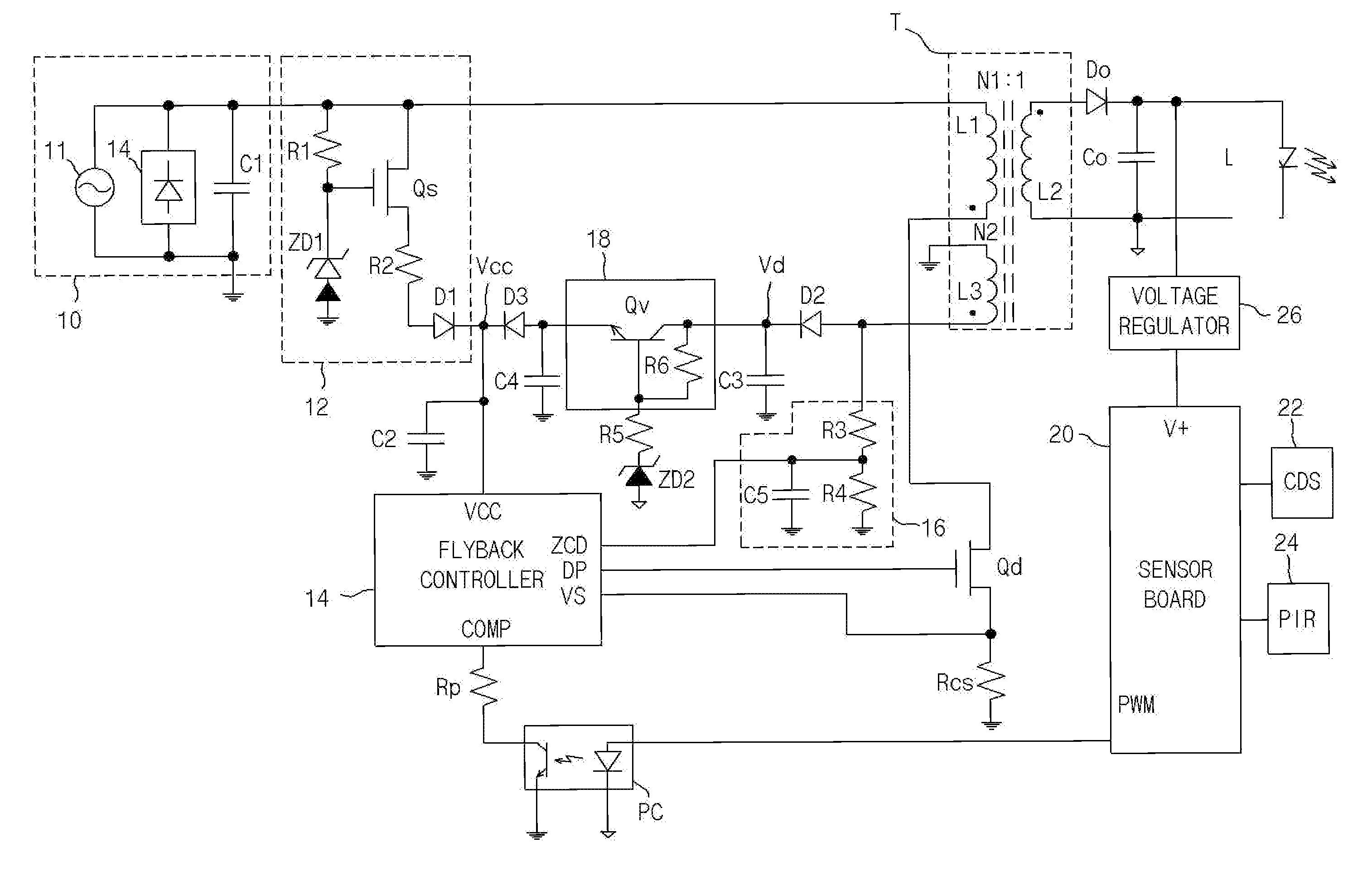
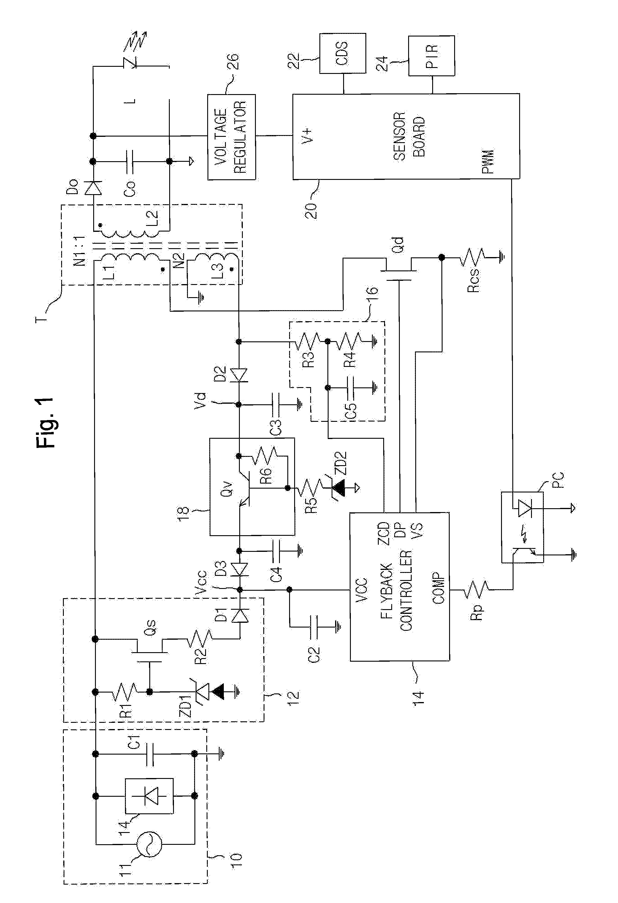
[0095]In the first embodiment, the winding ratio N2 of the auxiliary coil L3 may be set so that the auxiliary coil L3 outputs the detection voltage Vd as the driving voltage V1 having a level equal to the turn-off level of the LED lighting LED. That is, the detection voltage Vd can be set on the basis of a detection voltage Vd1 of FIG. 4.

[0096]For example, if the driving voltage V1 having a level equal to the turn-off level of the LED lighting LED is 18 V, the winding ratio N2 of the auxiliary coil L3 may be set so that the auxiliary coil L3 outputs the detection voltage Vd of the level 18 V.

[0097]Furthermore, the DC-DC regulator 18 may be configured to output the detection voltage Vd so that a maximum level of the detection voltage Vd satisfies an allowable range of the operating voltage Vcc.

[0098]In the first embodiment of the present invention in which the winding ratio N2 of the auxiliary coil L3 is set to the step-down state, the auxiliary coil L3 can output the driving voltage...

second embodiment

[0102]In contrast, in the present invention, the winding ratio N2 of the auxiliary coil L3 may be set so that the auxiliary coil L3 outputs the detection voltage Vd in response to the maximum driving voltage V2 of the LED lighting LED. That is, the detection voltage Vd may be set on the basis of a detection voltage Vd2 of FIG. 4.

[0103]For example, if the maximum driving voltage V2 of the LED lighting LED is 22 V, the winding ratio N2 of the auxiliary coil L3 may be set so that the auxiliary coil L3 outputs the detection voltage Vd of 22 V.

[0104]Furthermore, the DC-DC regulator 18 may be configured so that a minimum level of the detection voltage Vd satisfies an allowable range of the operating voltage Vcc.

[0105]In the second embodiment of the present invention in which the winding ratio N2 of the auxiliary coil L3 is set to the step-up state, the auxiliary coil L3 can output the detection voltage Vd corresponding to the maximum driving voltage of the LED lighting LED, that is, the d...

third embodiment

[0109]In contrast, in the present invention, the winding ratio N2 of the auxiliary coil L3 may be set so that the auxiliary coil L3 outputs the detection voltage Vd having a level corresponding to the middle of a driving voltage for driving the LED lighting LED. The detection voltage Vd can be set based on a detection voltage Vd3 of FIG. 4.

[0110]For example, if the center value of the driving voltage of the LED lighting LED is 20 V, the winding ratio N2 of the auxiliary coil L3 may be set so that the auxiliary coil L3 outputs the detection voltage Vd of 20 V.

[0111]Furthermore, the DC-DC regulator 18 may be configured so that a minimum level and a maximum level of the detection voltage Vd satisfy an allowable range of the operating voltage Vcc.

[0112]In the third embodiment of the present invention in which the winding ratio N2 of the auxiliary coil L3 is set to the step-up state, the auxiliary coil L3 can output the detection voltage Vd having a level corresponding to the center valu...


PUM


Abstract

Disclosed are a power supply apparatus for an LED lighting and an LED lighting apparatus using the power supply apparatus. The LED lighting apparatus includes a power source unit configured to supply a rectified voltage, a voltage converter configured to include at least one first inductor and to convert the rectified voltage, an auxiliary coil configured to include a second inductor and to supply a detection voltage corresponding to the current of the first inductor of the voltage converter, a controller configured to control the current of the voltage converter using a driving pulse generated in response to a control signal and a sensing voltage, and a voltage regulation circuit configured to regulate the detection voltage and to supply the regulated voltage as an operating voltage for the controller.

Description

BACKGROUND OF THE INVENTION[0001]1. Field of the Invention[0002]The present invention relates to a Light-Emitting Diode (hereinafter referred to as an ‘LED’) lighting, and more particularly, to a power supply apparatus for an LED lighting and an LED lighting apparatus using the power supply apparatus.[0003]2. Description of the Related Art[0004]In recent lighting apparatuses, incandescent lights and fluorescent lights are being replaced with LEDs capable of being implemented to have a relatively longer lifespan, low consumption power, and high brightness as lighting lamps.[0005]The lighting apparatus may include, for example, a security light and a streetlamp. An LED lighting apparatus that adopts an LED lighting is also developed as the security light or streetlamp and commercialized.[0006]An example of a conventional LED lighting apparatus is disclosed in Korean Patent Registration No. 10-1164631. In this patent, a commercial AC power source supplies a power to LEDs through a Swit...

Claims


Application Information

Patent Timeline
IPC IPC(8): H05B33/08H05B44/00
CPCH05B45/14H05B45/3725H05B45/385H05B45/12Y02B20/72Y02B20/30
Inventor KIM, YONG GUEN
Owner SILICON WORKS CO LTD
Why Eureka
Try Eureka