
Communication system and server

Active Publication Date: 2014-06-05
YAMAHA CORP
View PDF6 Cites 1 Cited by
  • Summary
  • Abstract
  • Description
  • Claims
  • Application Information

AI Technical Summary

Benefits of technology

The invention allows two devices located behind different routers to communicate with each other directly using specific addresses and ports. This is even possible when the destination address or port number changes. The invention allows for more efficient and secure communication between devices, regardless of their location or network.

Problems solved by technology

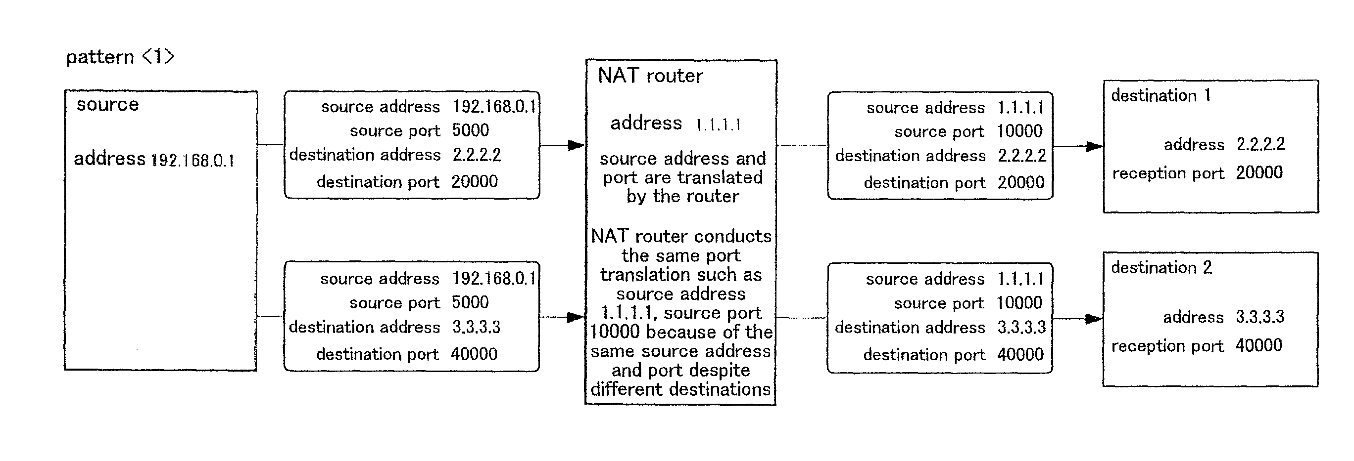
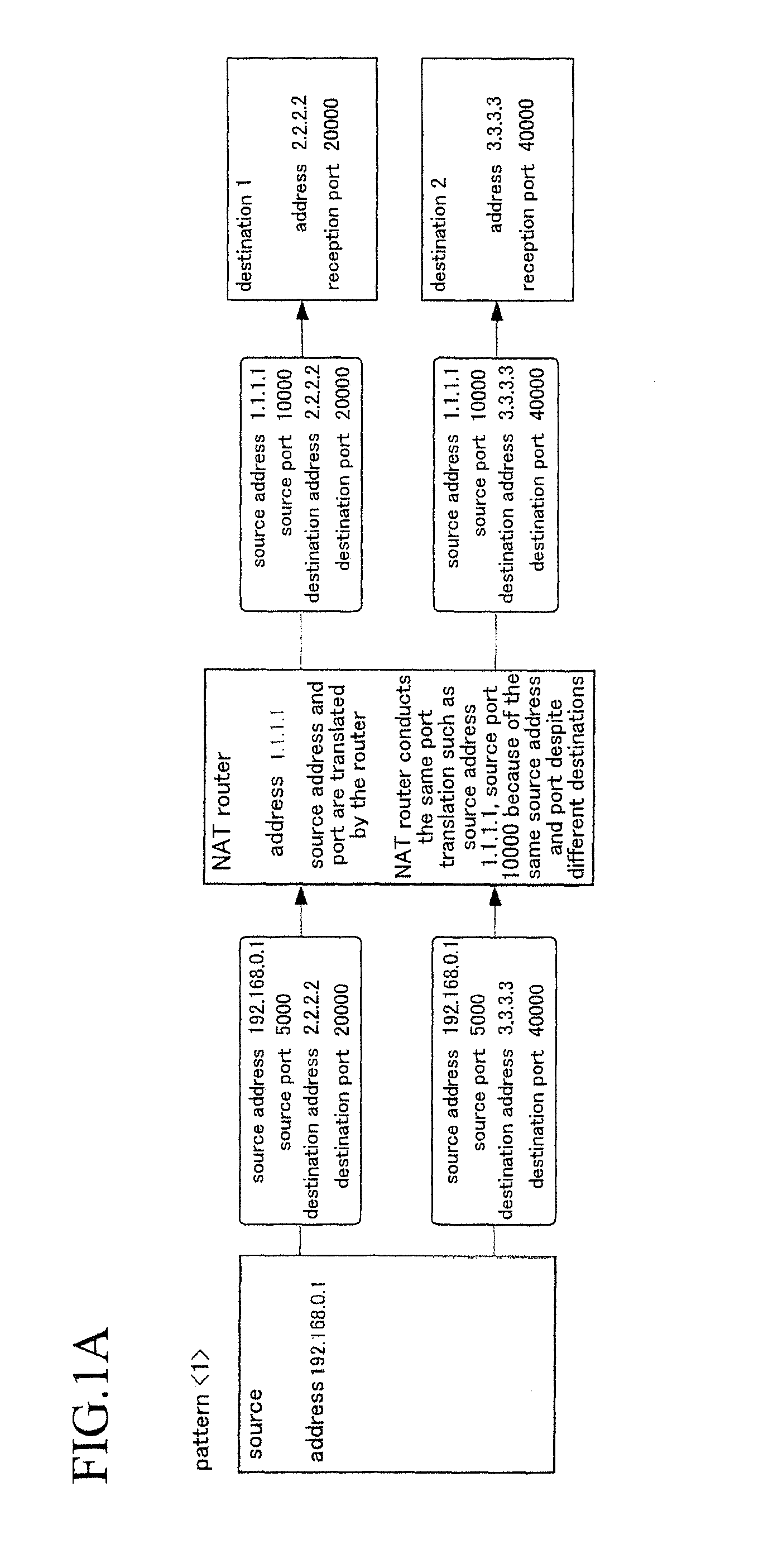
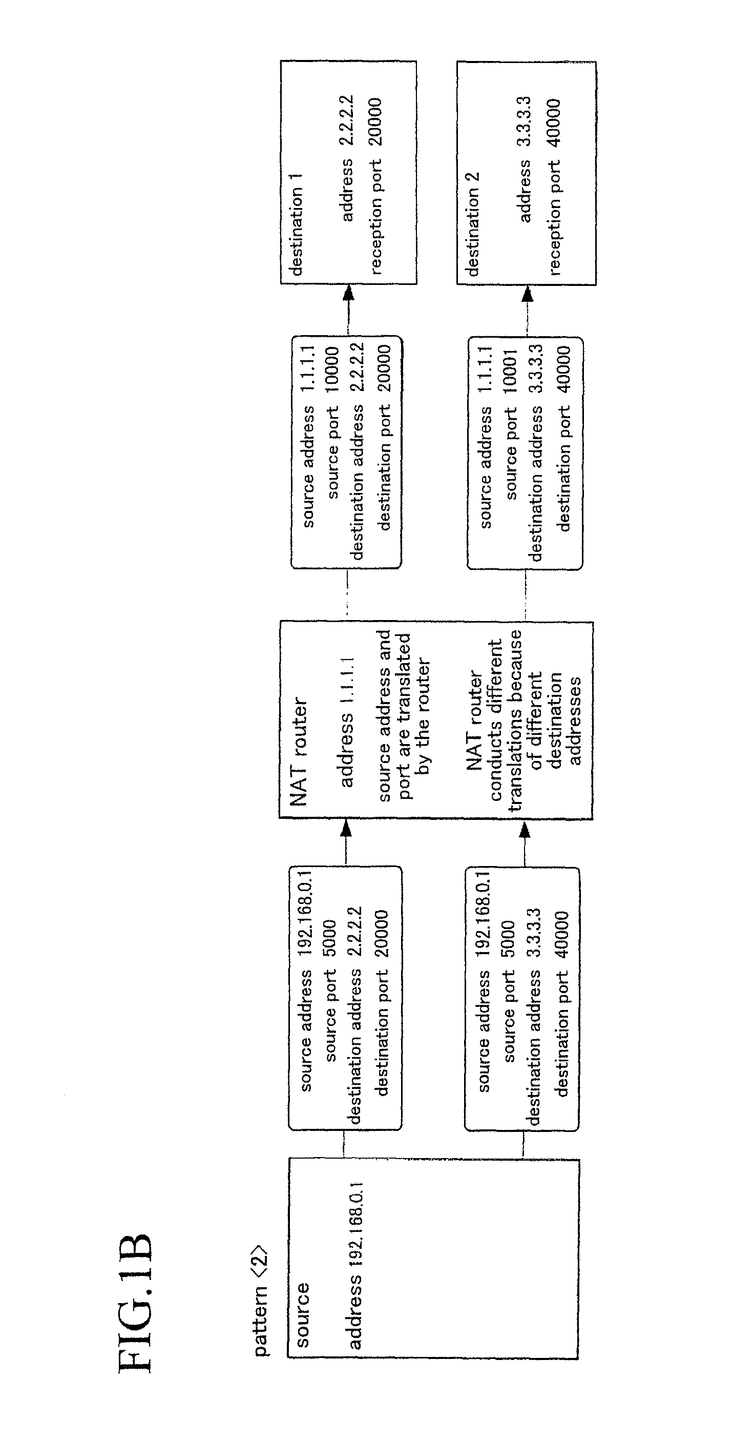
In spite of attempts to realize direct communication between the two terminals located behind different NAT routers, the connection between the two terminals cannot be established due to the above-described influence of translation of source address and source port number by the respective NAT routers unless the respective terminals can be informed of their respective partner's translated port number and address by any manner.
In a case, however, where both the NAT routers 1 and 2 are pattern of FIG. 1C, in other words, in a case of the NAT router which conducts different source port translations for packets having the same source address, source port number, and destination address but different destination port numbers, the UDP hole punching technique cannot cope with such type of NAT routers.
As a result, there will be no match that allows traverse.

Method used


Image

  • Communication system and server
  • Communication system and server
  • Communication system and server

Examples


first operation example

[0052]The first operation example will be explained. FIG. 4A and FIG. 4B indicate the first example connecting operation of the client terminal according to the embodiment of the invention. FIG. 5A and FIG. 5B indicate the first example connection assisting operation of the server according to the embodiment of the invention. In other words, FIG. 4A and FIG. 4B indicate a flowchart of a computer program according to the first example connecting operation, the program being executed by a CPU of the client terminal. FIG. 5A and FIG. 5B indicate a flowchart of a computer program according to the first example connection assisting operation, the program being executed by a CPU of the server.

[0053]In response to instructions to start connection by user's manipulation, the client terminal TM (the CPU serving as a control portion) starts executing the program indicated in FIG. 4A and FIG. 4B. At step C1, the client terminal TM informs the server SV of an attempt to establish connection. Th...

second operation example

[0071]Next, the second operation example will be explained. In the above-described first operation example, the server SV receives packets transmitted from the client terminals TM to the port numbers P1 and P2, and identifies respective types of the NAT routers behind which the client terminals TM are located on the basis of the source port numbers of the received packets. After the type identification, the server SV sends instructions for connection to the client terminals TM, respectively, so that, by use of packets transmitted to the port number P3 from the client terminals TM in response to the instructions, the server SV guesses respective port numbers of the NAT routers to send the guessed port numbers to the client terminals TM. In this second operation example, the server SV receives packets transmitted from the client terminals TM to the port numbers P1 and P2, identifies respective types of the NAT routers behind which the client terminals TM are located on the basis of so...


PUM


Abstract

In a communication system, using source address, source port number, destination address and destination port number, terminals A and B located behind NAT routers A and B, respectively, communicate with each other through the NAT routers A and B. A server SV which is not located behind any NAT routers identifies the NAT router A as a NAT router of a certain type which translates the source port number into a different source port number if the destination port number is changed. The server SV then guesses a port number obtained by adding (or subtracting) a value to (or from) the source port number used for transmission of data from the terminal A through the NAT router A as a port number of the terminal A in a case where the NAT router has been identified as the certain type, and informs the terminal B of the guessed port number.

Description

BACKGROUND OF THE INVENTION[0001]1. Field of the Invention[0002]The present invention relates to a communication system and a server which allow terminals located behind NAT routers, respectively, connected to a wide-area communication network such as Internet to communicate directly with each other.[0003]2. Description of the Related Art[0004]Conventionally, there are known network session systems that enable musical sessions such as ensemble performance of musical instruments and chorus such as duet through a wide-area communication network such as Internet. The session systems are designed such that performance information based on musical performance played on a terminal is transmitted to a different terminal via a wide-area communication network, and vice versa so that both the terminals can generate musical tones played by the terminals. In a case where the terminals are located behind NAT (Network Address Translation) routers (on the local side), respectively, however, it is ...

Claims


Application Information

Patent Timeline
IPC IPC(8): H04L12/741H04L45/74H04L45/741
CPCH04L45/74H04L61/2575H04L61/2557H04L61/2589
Inventor HARA, TAKAHIRO
Owner YAMAHA CORP
Features
  • Generate Ideas
  • Intellectual Property
  • Life Sciences
  • Materials
  • Tech Scout
  • Unparalleled Data Quality
  • Higher Quality Content
  • 60% Fewer Hallucinations
Learn More