
Magnetic Resonance Coil Apparatus

a magnetic resonance coil and coil technology, applied in the field of magnetic resonance coil apparatus, can solve the problems of affecting the examination of magnetic resonance, and affecting the patient's movement detection, so as to achieve the effect of reducing the examination time of the patien

Active Publication Date: 2014-06-12
SIEMENS HEALTHCARE GMBH
View PDF15 Cites 28 Cited by
  • Summary
  • Abstract
  • Description
  • Claims
  • Application Information

AI Technical Summary

Benefits of technology

The present invention improves the detection of patient movement during magnetic resonance examinations. This means that patient movement can be quickly and directly observed, and responses can be made quickly as well. This minimizes the time patients have to spend in the examination room, and the movement parameters can include information about the type of movement, speed, and frequency, among others.

Problems solved by technology

However, only rigid patient movement may be detected by the external marker elements and the conventional video camera.
If local magnetic resonance coils, however, are used for the magnetic resonance examination, movement detection by external marker elements and the conventional, externally disposed video camera may be problematic.
The arrangement and / or use of conventional, externally disposed video cameras for capturing patient movement data may also impede the magnetic resonance examination, in that the video cameras may restrict the receiving region for the patient because of the size and field of view of the video cameras.
Also, because of spatial extension, conventional video cameras may be disposed outside the patient examination region of the magnetic resonance apparatus and / or the local magnetic resonance coil, again impeding the detection of patient movement.

Method used


Image

  • Magnetic Resonance Coil Apparatus
  • Magnetic Resonance Coil Apparatus
  • Magnetic Resonance Coil Apparatus

Examples


Embodiment Construction

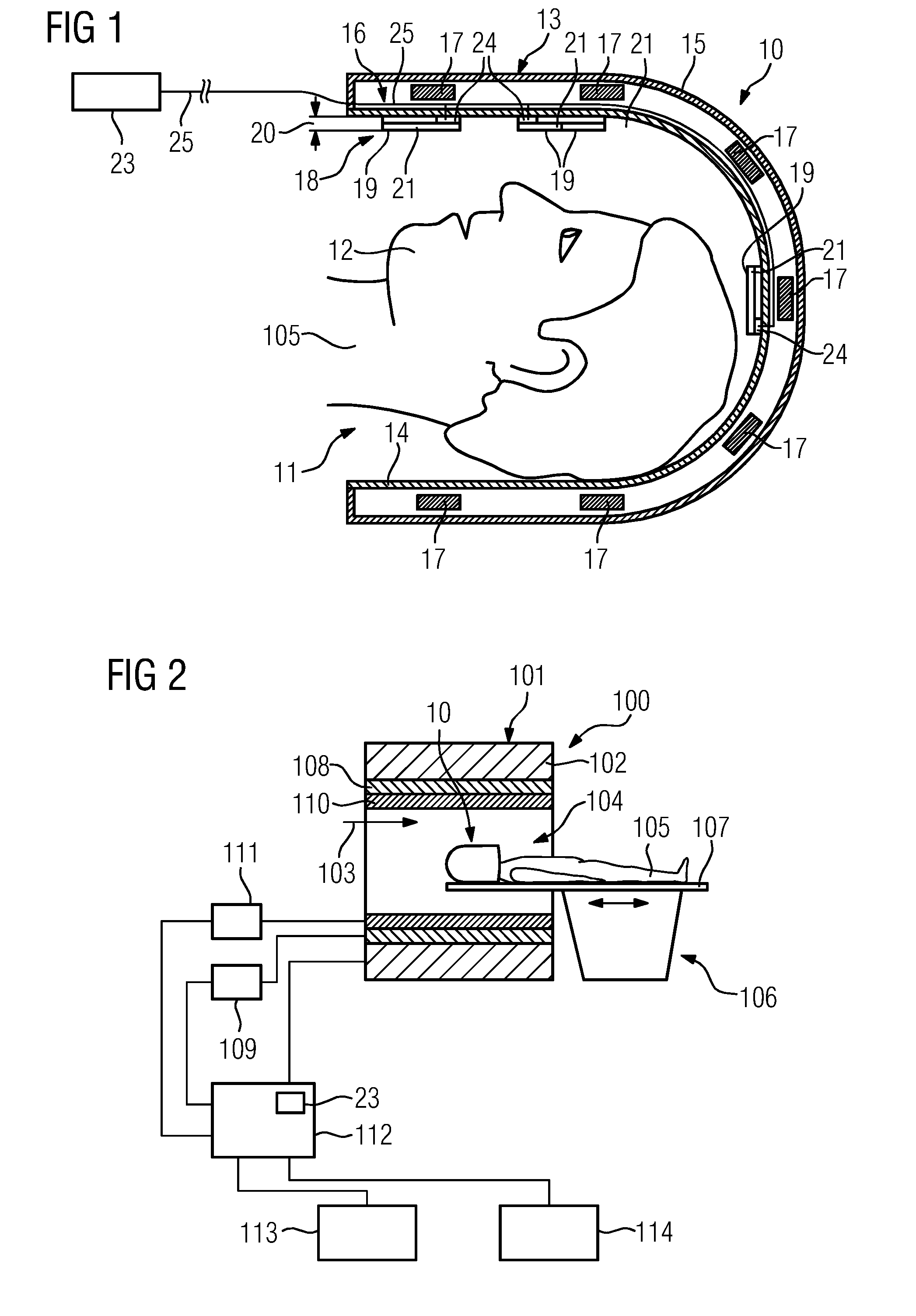
[0028]FIG. 1 shows a schematic representation of one embodiment of a magnetic resonance coil apparatus 10. In one embodiment, the magnetic resonance coil apparatus 10 is formed by a magnetic resonance head coil apparatus 10. Alternatively, the magnetic resonance coil apparatus 10 may also be formed by a magnetic resonance knee coil apparatus, a magnetic resonance chest coil apparatus, a further local magnetic resonance coil apparatus 10, or a combination thereof.

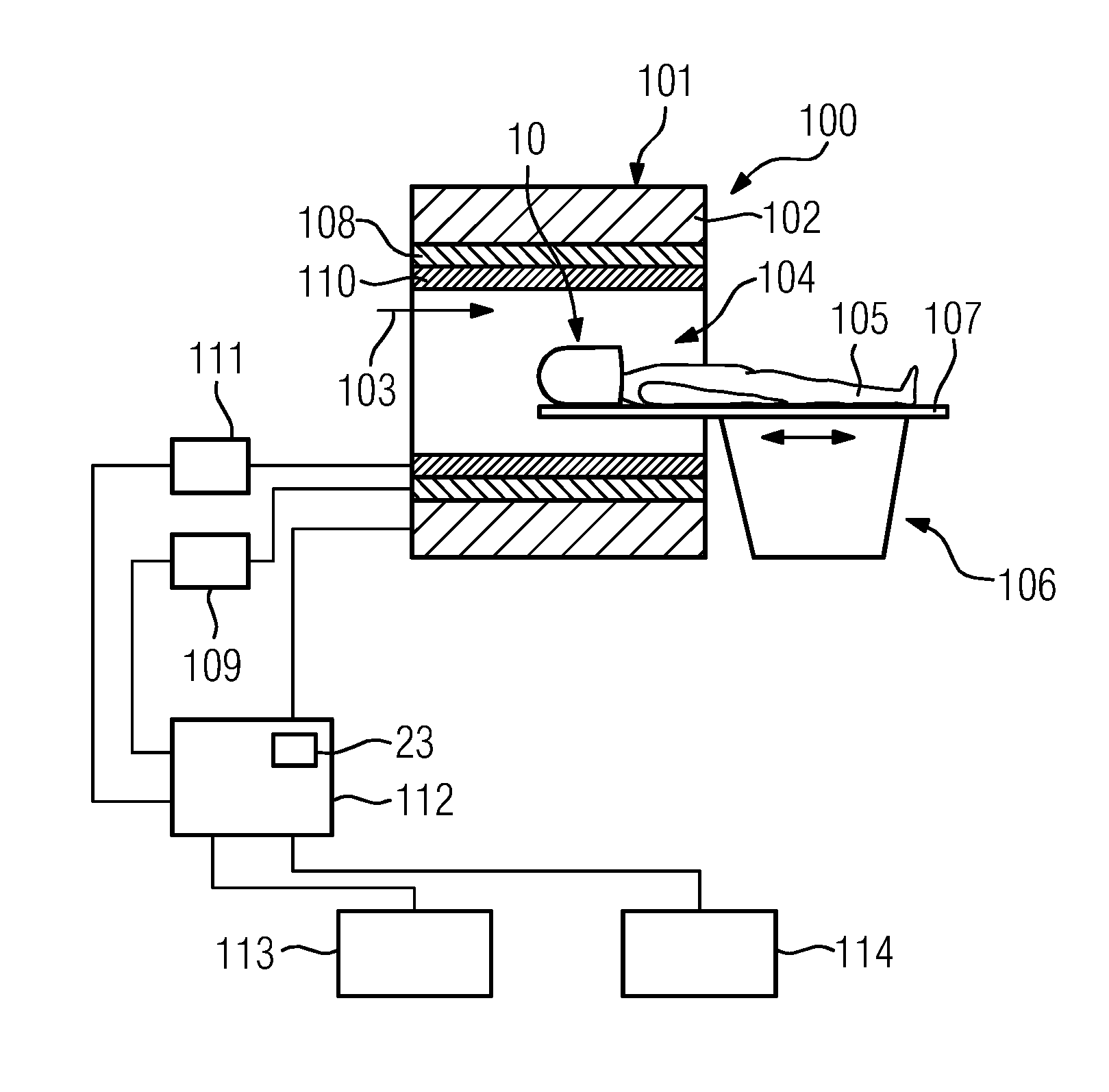
[0029]In one embodiment, the magnetic resonance coil apparatus 10 is installed in a fixed manner within a magnetic resonance apparatus 100 (FIG. 2) (e.g., a high-frequency antenna unit 110 that encloses a cylindrical patient examination region 104 of the magnetic resonance apparatus 100).

[0030]The magnetic resonance head coil apparatus 10 includes a receiving region 11 for receiving a head 12 of the patient 105 for, for example, head examinations. The magnetic resonance head coil apparatus 10 also includes a housing shell un...


PUM


Abstract

A magnetic resonance coil apparatus includes a receiving region for receiving a subregion of a patient to be examined, a housing shell unit enclosing the receiving region, and an antenna unit for picking up magnetic resonance signals. The magnetic resonance coil apparatus includes a camera unit with at least one light field camera element.

Description

[0001]This application claims the benefit of DE 10 2012 222 375.4, filed on Dec. 6, 2012, which is hereby incorporated by reference in its entirety.BACKGROUND[0002]The present embodiments relate to a magnetic resonance coil apparatus.[0003]A magnetic resonance examination may take up to an hour or longer for a patient to be examined. For the duration of a magnetic resonance examination, the patient may lie as still as possible on a patient support apparatus to prevent falsification of the measurement and / or artifacts in the magnetic resonance images.[0004]A distinction is made between two types of patient movement during the magnetic resonance examination: rigid patient movement and non-rigid patient movement. In the case of rigid patient movements, the object to be measured only moves in its entirety. Movement within the object does not take place (e.g., the head of the patient). In the case of non-rigid patient movements, however, the object may also change form and / or move (e.g.,...

Claims


Application Information

Patent Timeline
IPC IPC(8): G01R33/48
CPCA61B5/0077A61B5/11G01R33/34046G01R33/56509A61B5/055A61B5/702G01R33/48
Inventor GRODZKI, DAVID
Owner SIEMENS HEALTHCARE GMBH
Learn More