Devices And Methods For Emanating Liquids

a liquid flow and device technology, applied in the field of devices and methods for emanating liquids, can solve the problems of increasing the cost of aerosols containing such propellants, not being particularly convenient for routine use, and increasing the cost of use, so as to prevent the choking of the liquid flow

Inactive Publication Date: 2014-06-12
RECKITT & COLMAN OVERSEAS LTD
View PDF9 Cites 4 Cited by
  • Summary
  • Abstract
  • Description
  • Claims
  • Application Information

AI Technical Summary

Benefits of technology

[0018]The downstream valve is preferably operable to prevent any fluid within the refill from escaping until the downstream valve is opened and the upstream valve is operable to sealingly engage with liquid extraction means that are part of the emanation device which enter the refill to open a liquid pathway from the refill into the device. In this arrangement the downstream and upstream valves cooperate in that the downstream valve does not need to be optimised to seal against the liquid extraction means that open the valve as the upstream valve can be configured to undertake that task and, vice versa, the upstream valve need not be optimised to form a liquid-tight seal as the downstream seal can be optimised for that task. Furthermore, the open appearance of the upstream valve provides a user with a visual cue to aim either the liquid extraction means from the emanation device or use as a guide when loading the refill onto said means.
[0021]Advantageously the valve system(s) of the present invention may ameliorate, and for some types of liquid substantially completely remove, the damaging effects of fractionation as all the liquid and any naturally volatilised quantity thereof are retained within the refill until extraction is required.
[0024]The universal refill is preferably formed with a housing of rigid or substantially rigid material. Such an arrangement may be advantageous as differing forms of extraction of liquid therefrom may put different strains and pressures on the refill and by providing the housing of the refill in a rigid or substantially rigid material, the refill may be better able to resist those differing strains and pressures to deliver uniform and / or predictable characteristics.
[0027]The universal refill is preferably provided with a single reservoir. The presence of a diptube may be advantageous as this may better optimise the ability of the universal refill to operate in a number of different orientations when engaged with the chassis of an emanation device. The diptube may be connected to the valve system or may be held adjacent to the valve system by mounting fixed within the refill.
[0030]The refill housing is preferably provided with a section thereof adjacent the reservoir(s) that is substantially transparent to permit a user to easily determine what type of liquid is held therein and / or the level of said liquid.
[0034]Alternatively, where the universal refill is provided with a single aperture and single valve system, the blown air conduit and liquid conduit could be integrated such that the blown air conduit extends along a central core of the liquid conduit with the blown air conduit being provided with the greater length such that it can extend further into the refill and such that the conduits can enter the single aperture and valve system; the blown air conduit could be adjacent the liquid conduit however. In this arrangement the blown air conduit may act as described above by blowing air into the headspace of the refill to force liquid into the liquid conduit and into the device for emanation therefrom. As a further alternative, an integrated conduit can be provided with one conduit extending along a central core of the other conduit such that the conduits can both enter a single aperture and valve system, wherein the one conduit is a liquid conduit which has air blown across the top thereof to draw the liquid along the conduit via the Venturi effect and / or capillary effect, whilst the other conduit allows air to be returned to the reservoir to prevent choking of the liquid flow.

Problems solved by technology

Aerosols generally provide a satisfactory spray performance but since they require manual operation by a user, they are not considered to be particularly convenient for routine use.
Whilst the automation of the aerosol spraying devices overcomes the problem of manual operation of an aerosol canister, the use of aerosols containing such propellants is becoming increasingly less desirable since these volatile hydrocarbons carry the disadvantage of being flammable, the rising cost of oil is rendering them increasingly expensive and they also carry the further disadvantage of being an atmospheric source of carbon which is deemed to not be environmentally sensitive.
However, invariably the consumer is faced with a dilemma when purchasing any particular emanation device as the emanation method employed by the emanation device under consideration is not the only factor the consumer must also consider, the consumer must also consider the availability and range of refills of liquids to be used with said device.
In the field of air freshening in particular where the range of fragrances the consumer can select for use with the device is a key point of purchase consideration for the consumer, a small range of fragrances and / or fear that the refill range may not be supported in the long term may affect the consumer's true freedom of choice.

Method used


Image

  • Devices And Methods For Emanating Liquids
  • Devices And Methods For Emanating Liquids
  • Devices And Methods For Emanating Liquids

Examples


Embodiment Construction

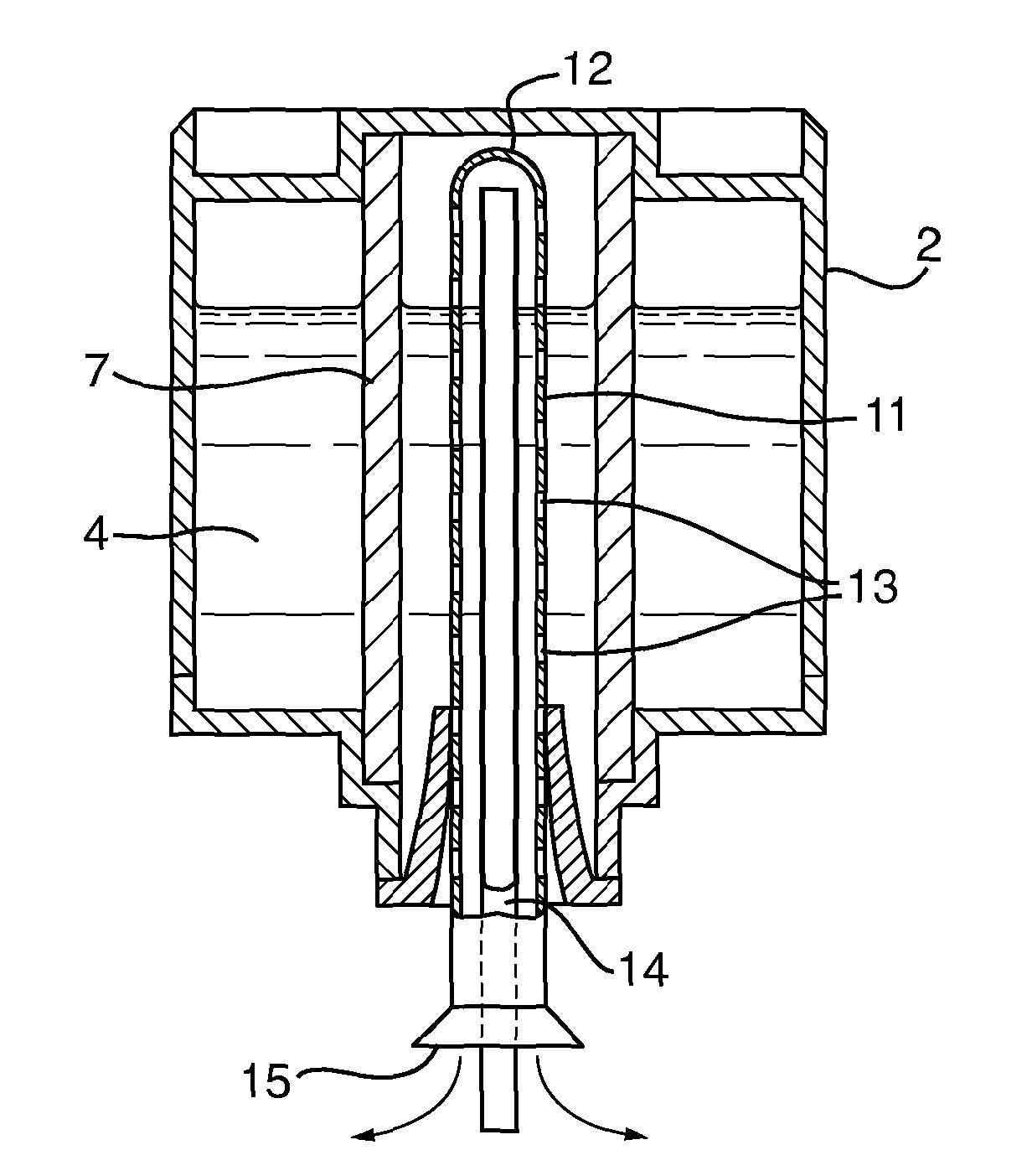
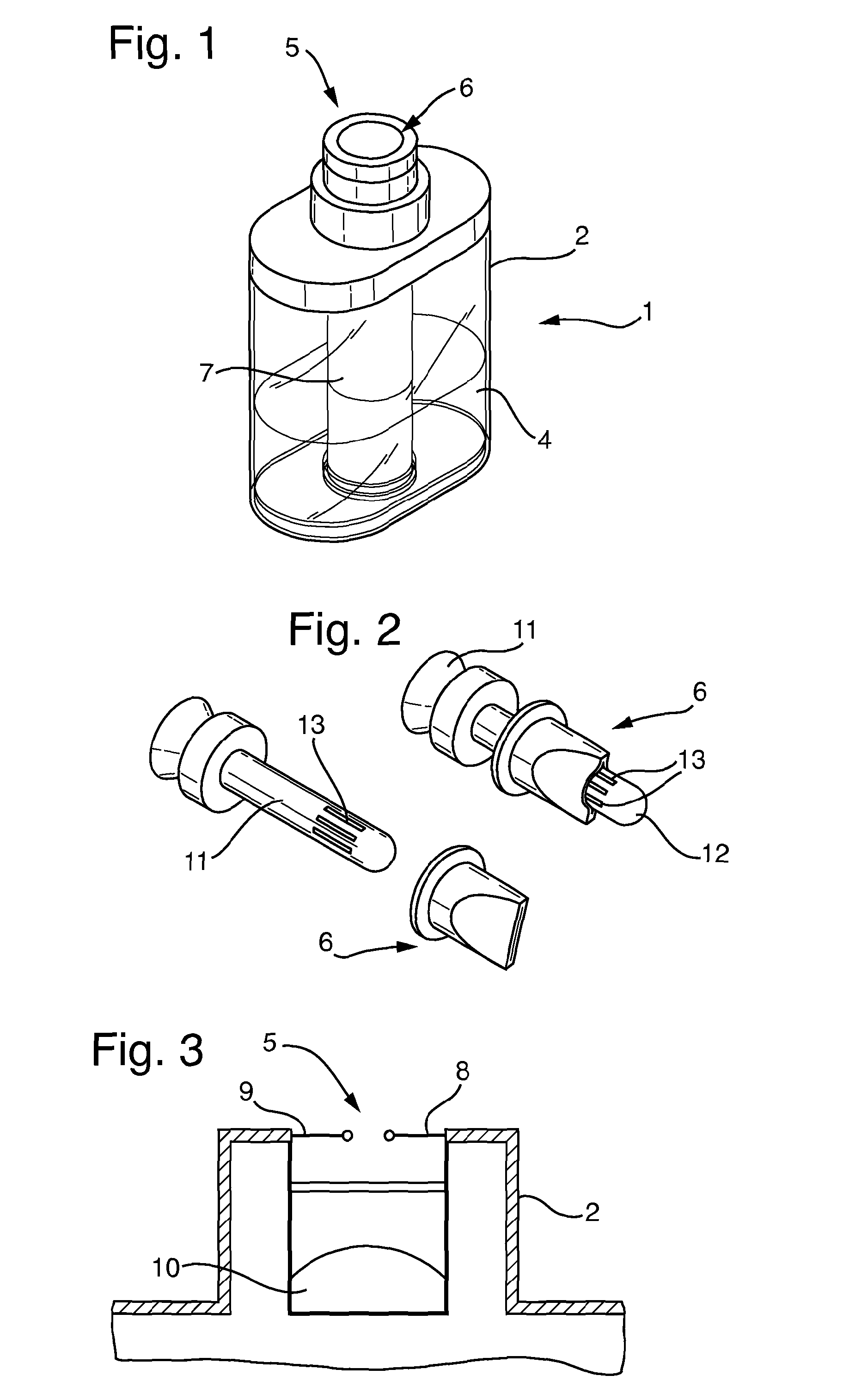
[0049]FIG. 1 shows a preferred embodiment of a refill 1 according to the present invention. The refill 1 comprises a housing 2 that surrounds and contains a reservoir 3 of liquid 4 therein. Access to the interior of the refill 1 and the reservoir 3 is provided via aperture 5 which is sealed by a valve 6. Housed entirely within the housing 2 of the refill 1 is a wick 7. The wick 7 is shown in FIG. 1 as a having a substantially cylindrical shape that extends from adjacent the valve 5 to contact a base of the reservoir 3.

[0050]Although not shown in FIG. 1, when the valve 6 is held in an open position, a notional elongate column of space within the interior of the housing extending from the perimeter of the valve opening to the lower wall of the housing is defined, hereinafter referred to as the elongate column. The wick 7 has a cylindrical shape that is hollow to substantially surrounds the elongate column.

[0051]FIG. 3 shows the valve 6 is greater detail. The valve 6 is an automaticall...


PUM

PropertyMeasurementUnit
electrically poweredaaaaaaaaaa
non-electrically aaaaaaaaaa
gravityaaaaaaaaaa

Abstract

A liquid dispensing system comprising a universal refill of liquid and an emanation device; wherein the refill comprises: a housing; at least one reservoir in the housing for holding the liquid; at least one aperture in the housing sealed by at least one valve wherein said at least one valve defines a liquid pathway from the reservoir to the exterior of the refill, wherein at least one of said valve(s) is configured to be automatically resealable when not being held open; at least one wick housed entirely within the housing; and wherein the emanation device is selected from: an emanation device configured to spray the liquid; an emanation device configured to evaporate the liquid by electrically powered means; an emanation device configured to evaporate the liquid by passive, non-electrically powered means; an emanation device configured to emanate the liquid by two or more of spraying the liquid, evaporating the liquid by electrically powered means and / or evaporating the liquid by passive, non-electrically powered means; characterised in that each emanation device is provided with a chassis configured to receive and releasably retain the universal refill and the universal refill is operationally compatible with each emanation device.

Description

FIELD OF THE INVENTION[0001]The present invention relates to devices and methods for improved airborne delivery of liquids containing one or more active materials wherein the active material comprises at least one of: a fragrance; an insecticide; a fungicide; a pesticide; a sanitising material; and / or a pharmaceutical.BACKGROUND[0002]Liquids, and commonly volatile liquids, containing one or more active materials wherein the active material comprises at least one of: a fragrance; an insecticide; a fungicide; a pesticide; a sanitising material; and / or a pharmaceutical are delivered within the domestic environment via a variety of mechanisms. Devices are available with heaters disposed therein to increase the rate of emanation from a surface saturated with the liquid, such a surface could be a wick saturated with a fragranced liquid and the heater is located adjacent the wick surface and nearby a chimney to heat the liquid on the wick surface and cause it to more readily evaporate and ...

Claims


Application Information

Patent Timeline
Patent Type & Authority Applications(United States)
IPC IPC(8): A61L9/03A61L9/12A61L9/14
CPCA61L9/037A61L9/14A61L9/127A61L9/032A61L9/122A61L2209/133A01M1/2044A61M11/00
Inventor STEPHENSON, HELEN
Owner RECKITT & COLMAN OVERSEAS LTD
Why Eureka
Try Eureka