Cartridge and method of manufacturing cartridge

Active Publication Date: 2014-06-12
CANON KK
View PDF3 Cites 4 Cited by
  • Summary
  • Abstract
  • Description
  • Claims
  • Application Information

AI Technical Summary

Benefits of technology

[0015]A second aspect of this disclosure provides a cartridge including: a first member having a flexible engaging portion; a second member having an engaged portion to be engaged with the engaging portion; and a third member configured to restrict a movement of the flexible engaging portion for maintaining a state in which the engaging portion and the engaged portion engage each other; wherein a width of the third member on the side closer to a base point of movement of the flexible engaging portion becomes larger than the width of the third member on the side farther from the base point of movement.
[0016]A third aspect of this disclosure is a cartridge including: a first member having a flexible engaging portion; a second member having a

Problems solved by technology

However, when the third member is mounted for restricting the first engaging portion from being bent, rattling may easily result between the first and second members and the third member as the restriction portion due to variations in dimension due to tolerances.
In particular, the rattli

Method used


Image

  • Cartridge and method of manufacturing cartridge
  • Cartridge and method of manufacturing cartridge
  • Cartridge and method of manufacturing cartridge

Examples


Example

Example 1

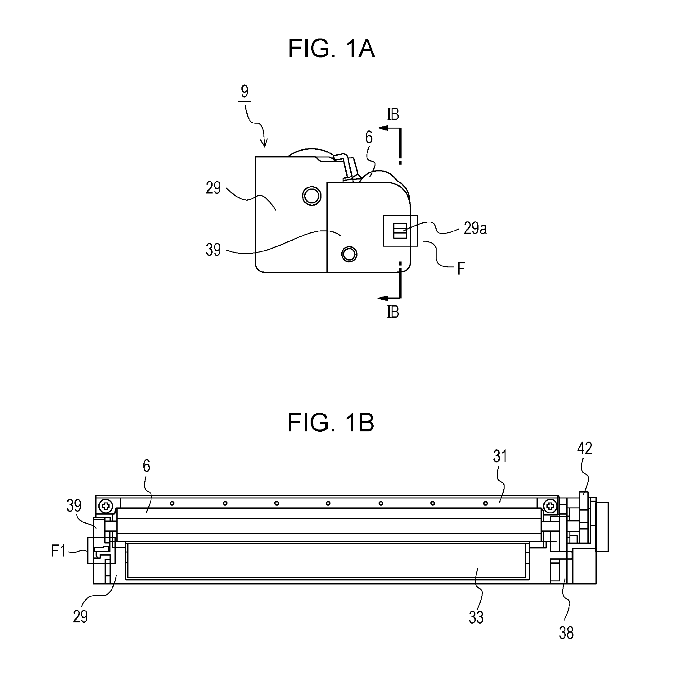
[0030]Referring now to FIG. 1A to FIG. 10B, examples of this disclosure will be described.

[0031]In the following embodiments, a full color laser printer in which four process cartridges including a developing apparatus are demountably mounted is exemplified as an image forming apparatus.

[0032]However, this disclosure is not limited to the printer, and may be applied to other image forming apparatuses such as copying machines and facsimile apparatuses, or other image forming apparatuses such as combined machines in which such functions are combined.

[0033]The number of process cartridges to be mounted on the image forming apparatus is not limited to four. The number of process cartridges may be set as needed.

[0034]For example, in a case of an image forming apparatus forming monochrome images, the number of the process cartridges to be mounted on the image forming apparatus is one.

[0035]In Example 1, a process cartridge including a developing apparatus will be described. Howev...

Example

Example 2

Configuration of Retention with Embedding Member for Fixation Between Development Frame Member and Nondrive-Side Bearing

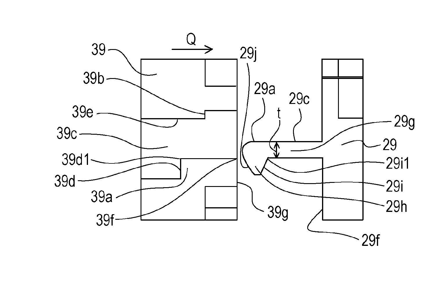
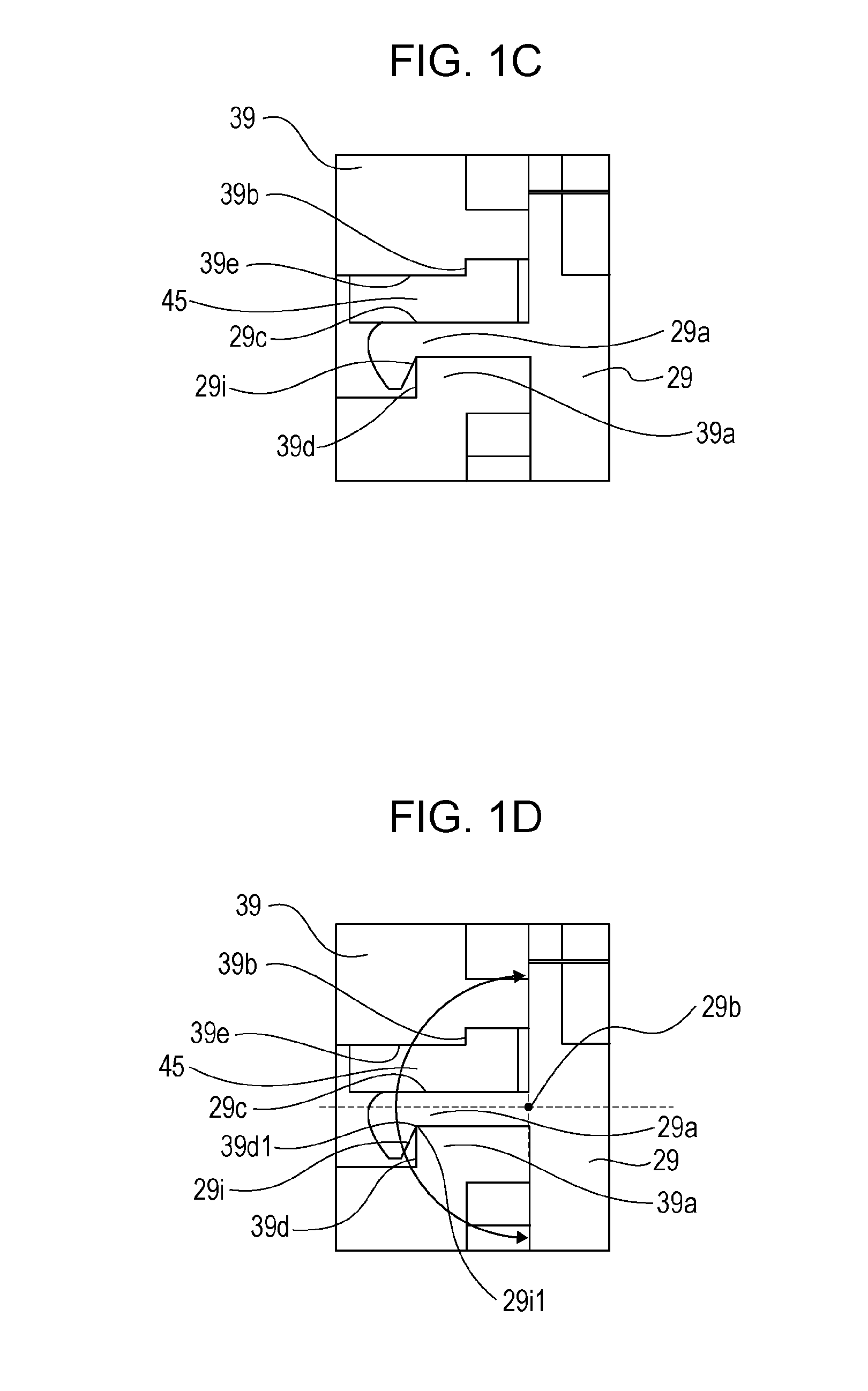
[0114]Referring now to FIG. 10 and FIG. 11, another form of this disclosure will be described as Example 2. In Example 1, the embedding member 45 is prevented from coming apart by bringing the retaining portion 45a of the embedding member 45 formed between the opposite surface 29c and the opposing surface 39e into contact with the retaining surface 39b of the nondrive-side bearing 39. In Example 2, a configuration of retention with an embedding member in another form will be described. Therefore, description overlapping with that of Example 1 will be omitted.

[0115]FIGS. 10A and 10B are detailed drawing illustrating a fixing portion between a developing frame 47 and a nondrive-side bearing 48. First of all, an engaging portion 47a provided on the developing frame 47 and an engaged portion 48d provided on the nondrive-side bearing 48 are engaged in the same ...


PUM

PropertyMeasurementUnit
Flexibilityaaaaaaaaaa
Widthaaaaaaaaaa

Abstract

A method of manufacturing a cartridge including a first member having a flexible engaging portion and a second member having an engaged portion to be engaged with the engaging portion, configured to manufacture a cartridge by a process of engaging the engaging portion of the first member and the engaged portion of the second member; and a process of forming a third member configured to restrict a movement of the flexible engaging portion by letting a fluent material flow in between the first member and the second member and solidifying the fluent material.

Description

BACKGROUND OF THE INVENTION[0001]1. Field of the Invention[0002]This disclosure relates to a cartridge configured to be demountably mounted to an electrophotographic image forming apparatus (hereinafter, referred to as “image forming apparatus”).[0003]The image forming apparatus is configured to form an image on a recording medium by using an electrophotographic system. Examples of the image forming apparatus include copying machines, printers (for example, laser beam printers, and LED printers), facsimile apparatuses, and word processors.[0004]The cartridge relates to a developing cartridge which is an integral cartridge including a developing device used for developing an electrostatic latent image on an electrophotographic photosensitive member and a process cartridge which is an integral cartridge including at least one of a charging device, a developing device, and a cleaning device which correspond to process devices and an electrophotographic photosensitive member which corre...

Claims


Application Information

Patent Timeline
IPC IPC(8): G03G21/18G03G15/08B21D39/03
CPCG03G15/0865G03G21/181G03G15/0875G03G21/1821Y10T29/49826
Inventor UNEME, TETSUSHI
Owner CANON KK
Why Eureka
Try Eureka