Apparatus and method for automatically controlling speed in speedbump area

Inactive Publication Date: 2014-06-12
HYUNDAI MOTOR CO LTD
View PDF2 Cites 16 Cited by
  • Summary
  • Abstract
  • Description
  • Claims
  • Application Information

AI Technical Summary

Benefits of technology

The present invention is a method and device that automatically controls the speed of a vehicle near speed bumps. It uses information from a navigation device and an automatic speed control system to accelerate or decelerate the vehicle in the speed bump area. This invention helps to make the driving experience smoother and more efficient for drivers.

Problems solved by technology

However, since such a conventional smart cruise control system cannot recognize a speed bump even if the speed bump is present in front of the corresponding vehicle, speed control is not adequately conducted in a speed bump area.
Therefore, the use of radar is problematic as it cannot recognize a speed bump and thus cannot automatically perform speed control (automatic cruise control) in response to detecting a speed bump.
In particular, the use of a camera is problematic in that if only the shape of a speed bump is drawn in a predetermined color on the roadway (without a speed bump actually being present on the roadway), the camera generally identifies a speed bump as being present and thus erroneously initiates an automatic speed control operation.
Meanwhile, Korean Patent Application Publication No. 10-2012-0119424 discloses technology entitled “Automatic cruise control system and method.” However, the technology disclosed in the publication cannot automatically control the speed of a vehicle in response to a speed bump.

Method used


Image

  • Apparatus and method for automatically controlling speed in speedbump area
  • Apparatus and method for automatically controlling speed in speedbump area
  • Apparatus and method for automatically controlling speed in speedbump area

Examples


Embodiment Construction

[0024]Hereinafter, embodiments of the present invention will be described in detail with reference to the attached drawings.

[0025]Reference now should be made to the drawings, in which the same reference numerals are used throughout the different drawings to designate the same or similar components.

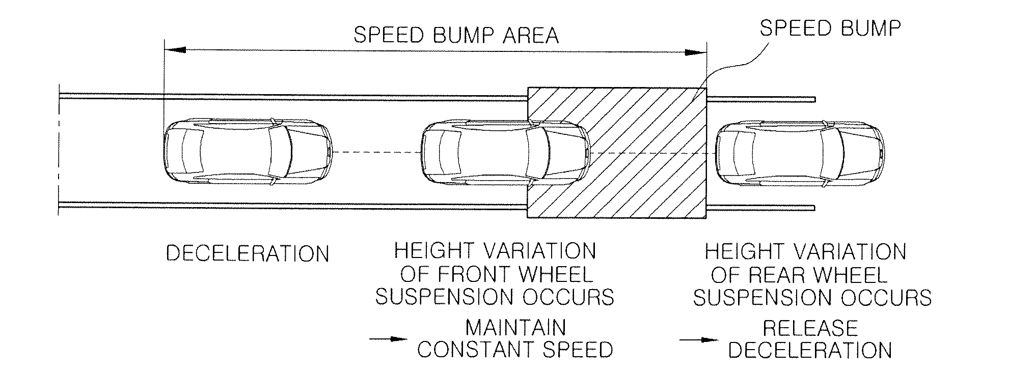
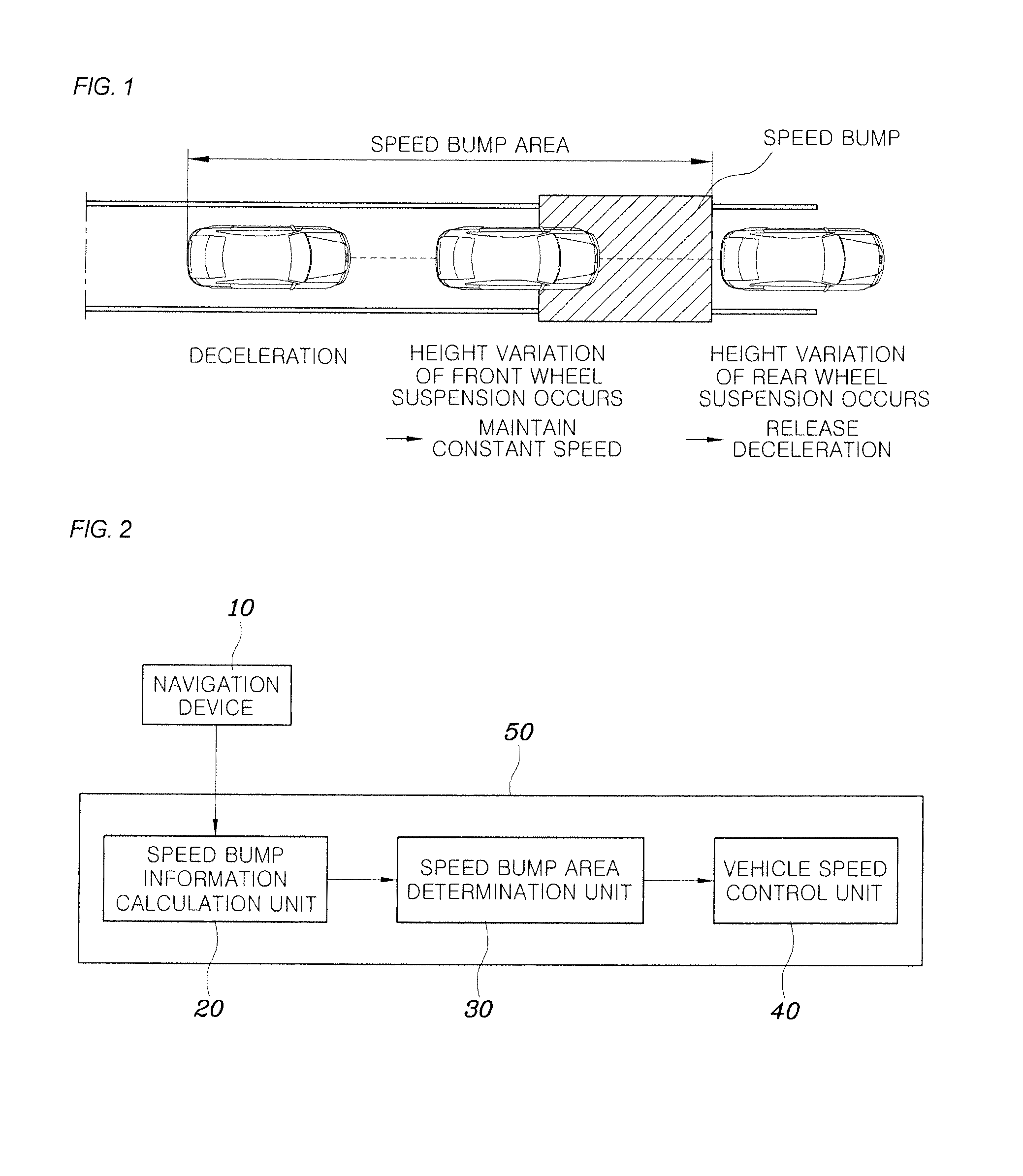
[0026]FIG. 1 is a diagram schematically showing a vehicle having its speed automatically controlled as the vehicle travels through a speed bump area according to the present invention, and FIG. 2 is a diagram showing an apparatus for automatically controlling speed in a speed bump area according to the present invention.

[0027]The method and apparatus for automatically controlling speed in a speed bump area according to the present invention are configured to allow a smart cruise control system to automatically control the speed of a vehicle in a speed bump area located in front of the corresponding vehicle. The method and apparatus rely at least in part on road information obtained by a n...


PUM


Abstract

The speed of a vehicle is automatically controlled in a speed bump area located in the vicinity of a speed bump. Information about a speed bump is received from a navigation device, and a distance between the vehicle and the speed bump is calculated. If the calculated is less than a preset reference distance, it is determined that the vehicle is entering or has entered an area of the speed bump. Upon determining that the vehicle is in the speed bump area, a speed difference between a safe speed bump crossing speed and a current speed of the vehicle is computed, a required acceleration value is calculated based on the calculated distance to the speed bump and the speed difference, and the speed of the vehicle is controlled so that the vehicle decelerates or is accelerates in accordance with the required acceleration value.

Description

CROSS-REFERENCE TO RELATED APPLICATION[0001]This application claims the benefit under 35 U.S.C. §119(a) of Korean Patent Application No. 10-2012-0142056, filed Dec. 7, 2012, the entire contents of which are incorporated herein by reference.BACKGROUND OF THE INVENTION[0002]1. Field of the Invention[0003]The present invention relates, in general, to automatic speed control technology for vehicles and, more particularly, to a method and apparatus for automatically controlling speed in the vicinity of a speed bump. The method and apparatus can, for example, automatically control the speed of a vehicle so that the vehicle accelerates or decelerates in the speed bump area by combining speed bump information input from a navigation device with an automatic speed control system.[0004]2. Description of the Related Art[0005]A smart cruise control system denotes a system for performing speed control so that the speed of one vehicle is maintained at the speed set by a driver when there is no pr...

Claims


Application Information

Patent Timeline
IPC IPC(8): B60K31/00
CPCB60W30/143B60W2510/22B60W2720/106B60W2555/60B60W2556/50B60W30/14B60W40/06G01C21/26
Inventor UM, DAE YOUNKIM, JEE YOUNG
Owner HYUNDAI MOTOR CO LTD
Why Eureka
Try Eureka