Stereoscopic camera object detection system and method of aligning the same

Active Publication Date: 2014-06-19
SAMSUNG ELECTRONICS CO LTD
View PDF2 Cites 57 Cited by
  • Summary
  • Abstract
  • Description
  • Claims
  • Application Information

AI Technical Summary

Benefits of technology

[0006]Described herein is a system, a controller for the system, and a method that uses multiple images from stereoscopic cameras to determine an observed displacement of an object, and compares that observed displacement to a predicated displacement based on motion of the vehicle on which the system is mounted. The comparison is used to compensate for misalignment of the stereoscopic cameras. By way of further explanation and not limitation, as the vehicle travels, objects in the field of view of the cameras will change positions or “flow” within the captured images. If

Problems solved by technology

Any misalignment of the cameras will cause additional unexpected or unknown disparity between the observed displacement, and the predicted di

Method used


Image

  • Stereoscopic camera object detection system and method of aligning the same
  • Stereoscopic camera object detection system and method of aligning the same
  • Stereoscopic camera object detection system and method of aligning the same

Examples


Embodiment Construction

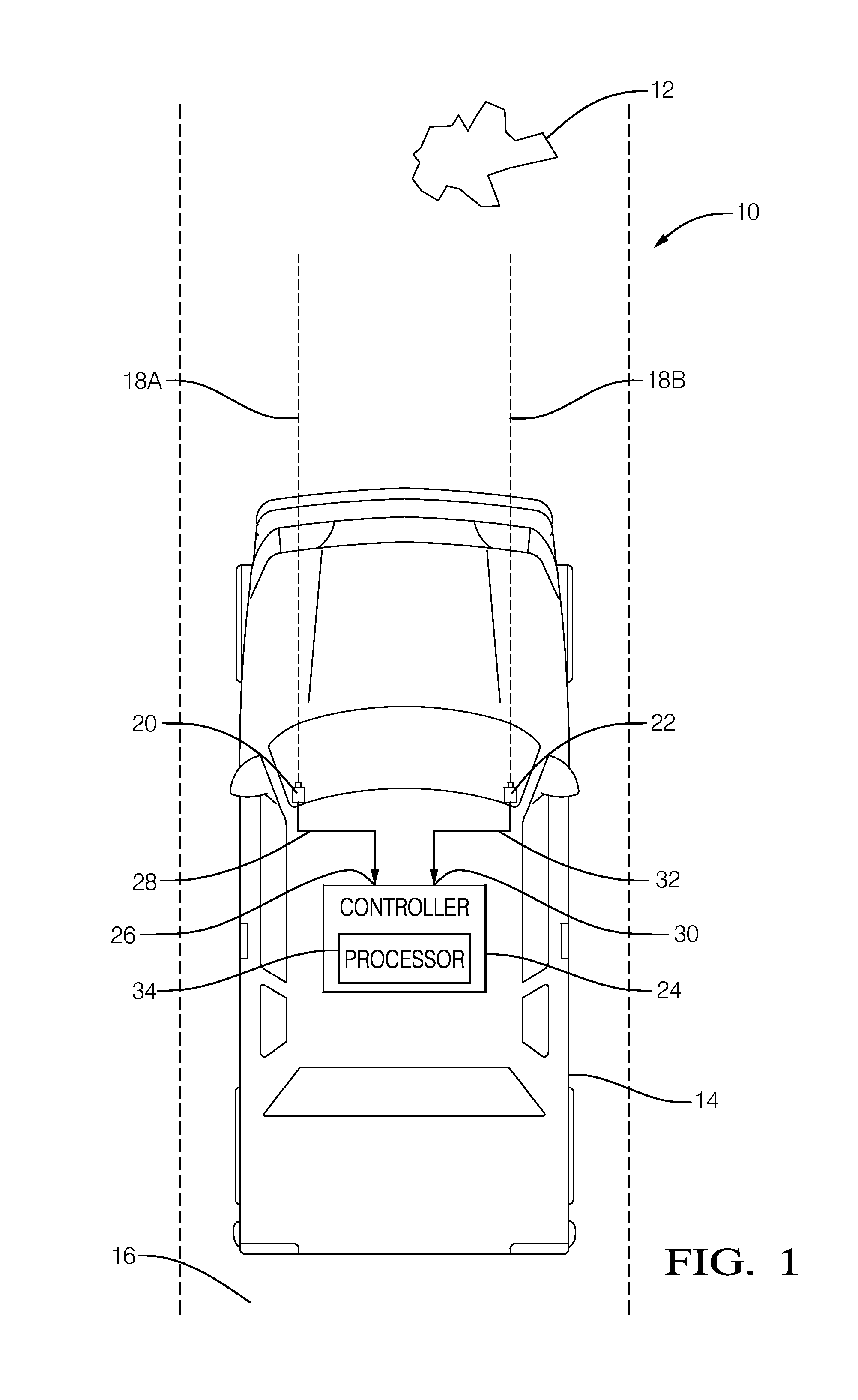
[0023]One way to improve the performance of a stereoscopic vision system is to devise a way to align ‘electronically’ the images captured by the individual cameras so that maintaining alignment does not rely on a rigid mounting structure. This will further improve system performance by allowing for increased separation distance between the cameras, while avoiding the undesirable cost, mass, ergonomic, and practical limitations of a common mounting structure. Stereoscopic cameras for vehicles that are mounted on a common structure with a separation of 250 to 300 millimeters between optical centerlines of the cameras are known. The teachings presented herein allow the cameras to be mounted on opposite sides of the vehicle, thereby achieving a separation of 1000 millimeters (1 meter) or more between optical centerlines. Increasing the separation distance by a factor of four will increase the ranging accuracy by a factor of four. The teachings presented herein provide this improvement w...


PUM


Abstract

A system, controller, and method for aligning a stereo camera of a vehicle mounted object detection system that includes a first camera and a second camera mounted spaced apart on a vehicle. An image from each camera at two different times is used to determine an observed displacement of an object relative to the vehicle. A predicted displacement of the object relative to the vehicle is also determined using either a difference of vehicle position measured based on other vehicle measurements or GPS, or a difference of size of the object in images taken at the two different times. Alignment is provided by determining a triangulation correction based on a difference of the observed displacement and the predicted displacement to correct for misalignment of the cameras.

Description

TECHNICAL FIELD OF INVENTION[0001]This disclosure generally relates to a stereoscopic camera object detection system for a vehicle and a method for aligning the cameras of the system, and more particularly relates using a secondary means to estimate relative motion or displacement between the object and the vehicle to determine a triangulation correction or triangulation offset to correct for misalignment of the cameras when determining object location based on triangulation of images from the cameras.BACKGROUND OF INVENTION[0002]Driver assistance systems gather information about an area proximate to a vehicle to provide better awareness to an operator of the vehicle regarding, for example, other vehicles and objects in the travel path of the vehicle. This information can be sensed with numerous technologies. The development of affordable and reliable digital vision technology allows for providing vision based object detection systems. Monocular vision systems using a single camera ...

Claims


Application Information

Patent Timeline
IPC IPC(8): H04N13/02
CPCG06T2207/10021G06T2207/30252G06T7/85H04N13/246
Inventor CLUFF, CHARLES A.TAYLOR, RONALD M.
Owner SAMSUNG ELECTRONICS CO LTD
Why Eureka
Try Eureka