Integrated vision system

a vision system and integrated technology, applied in the direction of pedestrian/occupant safety arrangements, vehicular safety arrangements, instruments, etc., can solve the problems of insufficient view data collected by image sensors such as infrared cameras, milli-wave radars and laser radars, and the 3-d map data cannot follow actual changing geographical conditions, etc., to meet the requirements of a driver or pilot. , the pseudo-view generated based on the data does not meet the requirements of the driver or pilo

Inactive Publication Date: 2001-12-06
SUBARU CORP
View PDF19 Cites 49 Cited by
  • Summary
  • Abstract
  • Description
  • Claims
  • Application Information

AI Technical Summary

Benefits of technology

0009] A purpose of the present invention is to provide an integrated vision system that offers crew on a vehicle with almost real pseudo views at high visibility like in a good whether even at low visibility with detection of obstacles to the front for safe and sure flight or driving.

Problems solved by technology

View data collected by the image sensors such as an infrared camera, a milli-wave radar and a laser radar are, however, not sufficient for a driver or pilot.
Moreover, 3-D map data cannot follow actual changing geographical conditions.
Pseudo-views generated based on these data therefore do not meet the requirements of a driver or pilot.
In detail, infrared cameras can be used at certain level of low visibility, particularly, can generate extremely clear images at night, however, lack in reality, perspective and feeling of speed due to monochrome images.
Milli-wave radars can cover relatively long rage even in rainy weather, thus useful in image displaying at low visibility, however, cannot generate clear images due to wavelength extremely longer than light, thus not sufficient for a driver or pilot.
Laser radars have an excellent obstacle detecting function, however, take long for scanning a wide area, thus revealing low response.
For a narrow scanning area, they provide relatively clear images, but, narrow views for a driver or pilot, thus not sufficient for safety.
These data, however, may not match actual land features and obstacles.
Such image generation thus has a difficulty in covering newly appearing obstacles and requires a lot of confirmation of safety.

Method used


Image

  • Integrated vision system
  • Integrated vision system

Examples


Embodiment Construction

[0013] Preferred embodiments according to the present invention will be disclosed with reference to the attached drawings.

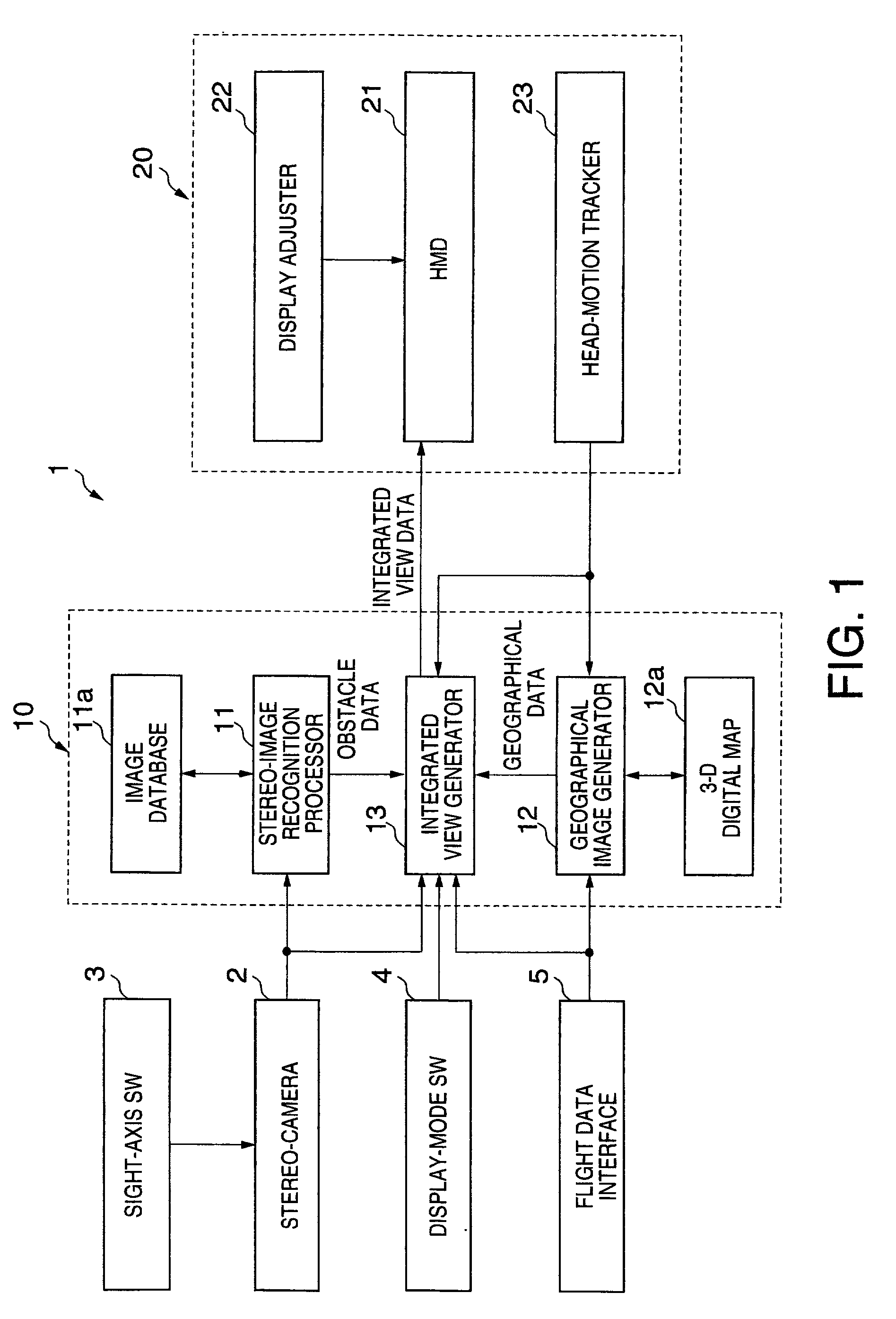
[0014] An integrated vision system 1 shown in FIG. 1 is installed in a vehicle such as an automobile, a train, and an aircraft. The system 1 offers integrated views to a driver or pilot generated as visible images of virtual reality at high visibility like in good weather even though actual visibility is very low in bad weather due to mist or fog, or at night.

[0015] Disclosed hereinafter is an embodiment in which the integrated vision system 1 is installed in an aircraft such as a helicopter that flies at relatively low altitude.

[0016] The integrated vision system 1 is provided with a stereo-camera 2 for taking images of forward scenery of a predetermined area, an image combining apparatus 10 and an integrated view displaying apparatus 20 as main components.

[0017] A pair of left and right images taken by the stereo-camera 2 are displayed on left and right viewing...


PUM


Abstract

An integrated vision system is disclosed. Images of outside area are taken by at least one stereo-camera installed in a vehicle. A pair of images taken by the stereo-camera are processed by a stereo-image recognizer for recognition of objects that are obstacles to the front, thus generating obstacle data. Integrated view data including three-dimensional view data are generated by an integrated view data generator based on the pair of images and the obstacle data. The integrated view data are displayed by an integrated image display as visible images to crew on the vehicle.

Description

BACKGROUND OF THE INVENTION[0001] The present invention relates to an integrated vision system that provides crew on vehicle with views of high visibility even at actually low visibility.[0002] Vehicles, for example, aircraft are provided with a vision system having image sensors such as an infrared camera, a milli-wave radar and a laser radar. The vision system offers a driver or pilot with artificial pseudo-views generated based on view data collected by the image sensors at low visibility at night or in bad weather and three-dimensional (3-D) map data stored in the system for safety.[0003] Japanese-Unexamined Patent Publication No. 11-72350 discloses generation of pseudo-views using wide-area geographical data based on 3-D map stored in memory and data on obstacles such as high-voltage electrical power lines, skyscrapers and cranes and displaying pseudo-views and actual views overlapping with each other on a transparent-type display mounted on a helmet of a pilot.[0004] View data...

Claims


Application Information

Patent Timeline
Patent Type & Authority Applications(United States)
IPC IPC(8): B64D47/08B60R21/01B60R21/0134B60W30/00G01C11/02G06T1/00G08G1/16G08G5/04H04N7/18H04N13/00
CPCB60R21/013H04N19/597G01C11/02H04N13/0037H04N13/004H04N13/0055H04N13/0239H04N13/0257H04N13/0278H04N13/0289H04N13/0296H04N13/044H04N13/0443H04N13/0456H04N13/0475H04N13/0477H04N13/0481H04N13/0484H04N2013/0081B60R21/0134H04N13/15H04N13/156H04N13/189H04N13/239H04N13/257H04N13/279H04N13/289H04N13/296H04N13/344H04N13/346H04N13/361H04N13/373H04N13/376H04N13/38H04N13/383
Inventor TAKATSUKA, TAKESHISUZUKI, TATSUYAOKADA, HIROSHI
Owner SUBARU CORP
Why Eureka
Try Eureka