Object recognizing apparatus

a technology of object recognition and apparatus, applied in the field of object recognition apparatus, can solve the problems of excessively early or excessive delay, non-reachable pertinent control timing, and bringing about dispersion

Inactive Publication Date: 2007-12-13
SUBARU CORP
View PDF3 Cites 55 Cited by
  • Summary
  • Abstract
  • Description
  • Claims
  • Application Information

AI Technical Summary

Benefits of technology

[0021] The object recognizing apparatus according to the invention can execute a control based on a result of recognizing the object by a pertinent timing against uncertain factors

Problems solved by technology

Although according to such a technology of recognizing an object, generally, there are used recognizing sensors represented by a camera, a millimeter wave radar, a laser radar and the like, the recognizing sensors pose a problem that a dispersion is brought about in a detecting accuracy by a running environment.
However, only by determining an object simply by a height of a probability distribution as disclosed in Patent Reference 1, there is a concern that b

Method used


Image

  • Object recognizing apparatus
  • Object recognizing apparatus
  • Object recognizing apparatus

Examples


Embodiment Construction

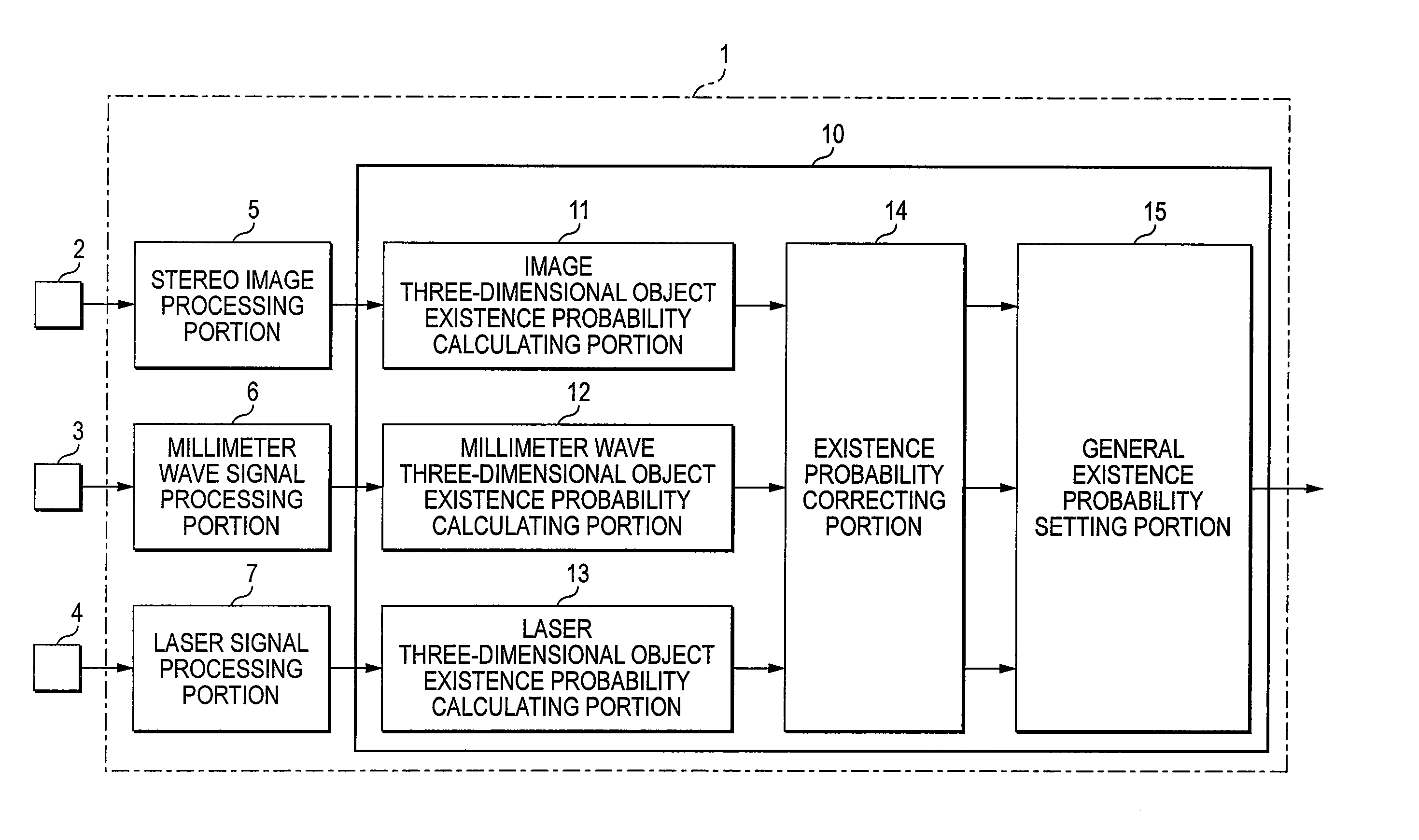
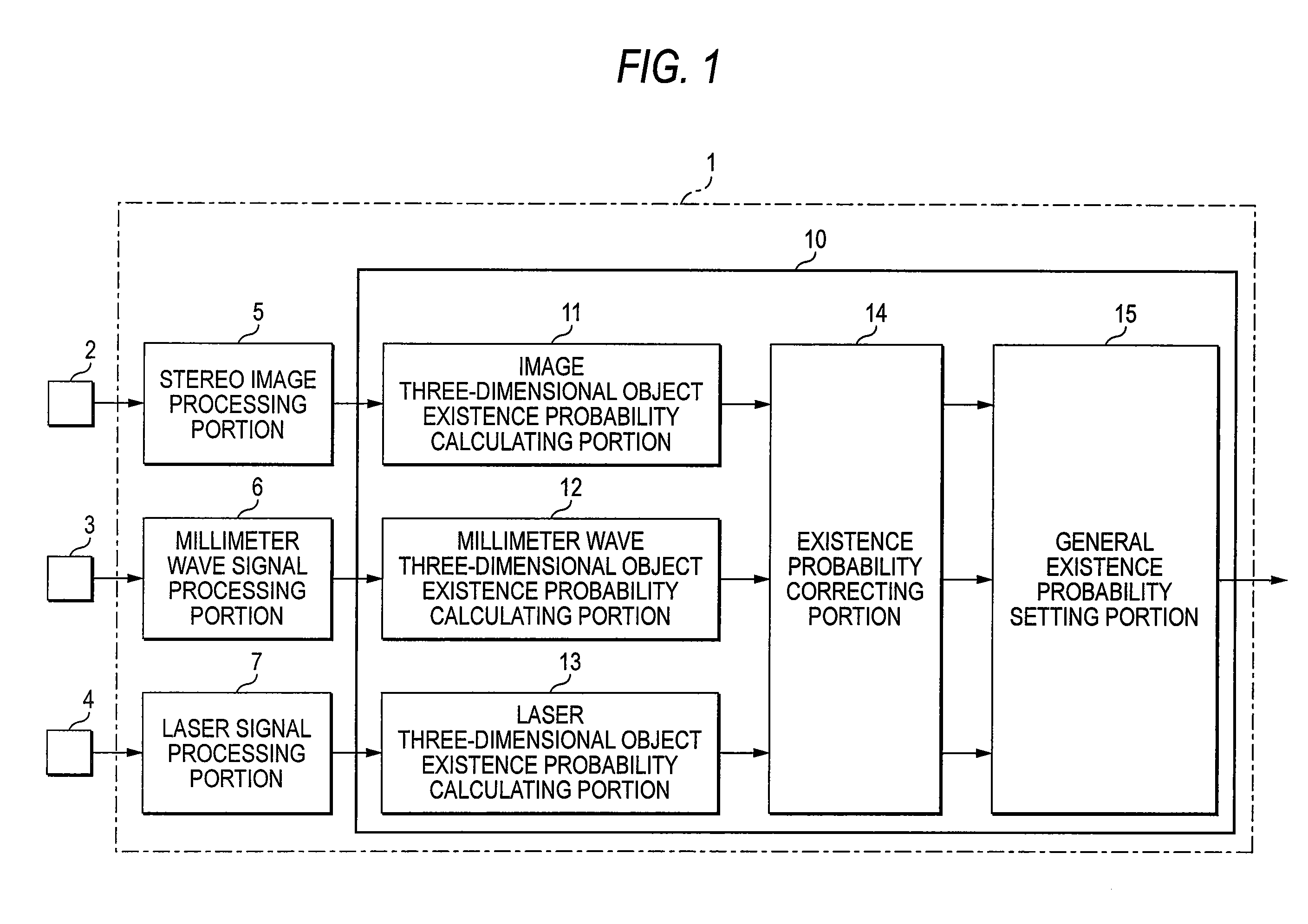
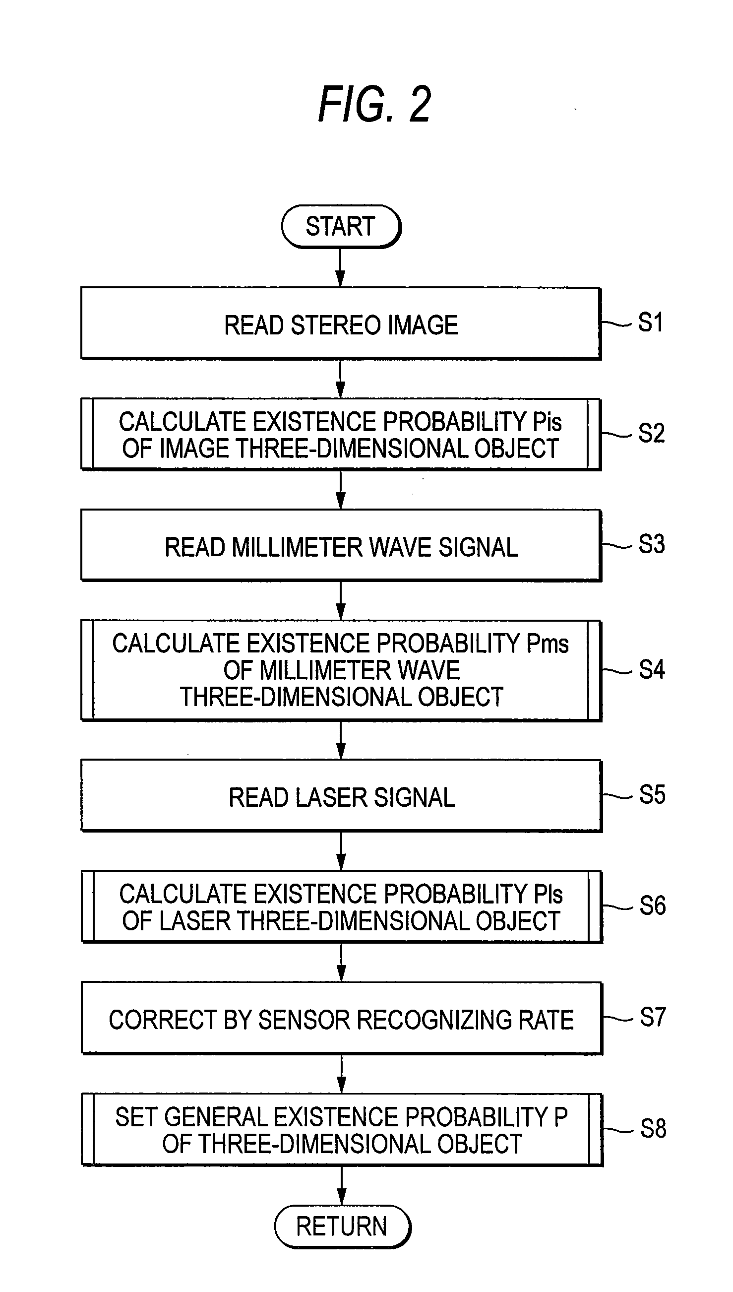
[0028] Embodiments of the invention will be explained in reference to the drawings as follows. FIG. 1 to FIG. 5 relate to a first mode of the embodiments of the invention, FIG. 1 is a block diagram of an object recognizing apparatus, FIG. 2 is a flowchart of a fusion existence probability calculating processing, FIG. 3 is a flowchart showing an existence probability calculating processing of an object by a recognizing sensor, FIG. 4 is an explanatory view showing transition of a statistical position of an object constituting an object of determination, FIG. 5 is an explanatory view of an existence probability.

[0029] In FIG. 1, notation 1 designates an object recognizing apparatus mounted on a vehicle of an automobile or the like for recognizing an object including a three-dimensional object by processing a signal from a recognizing sensor for detecting an outside field situation, which outputs a result of recognizing the object to a vehicle control apparatus, not illustrated, for m...


PUM


Abstract

An existence probability of an image object based on an image taken by a stereo camera 2 is calculated by an image object existence probability calculating portion 11, an existence probability of a millimeter wave object based on an output of a millimeter wave radar 3 is calculated by a millimeter wave object existence probability calculating portion 12, and an existence probability of a laser object based on an output of a laser radar 4 is calculated by a laser object existence probability calculating portion 13. Further, the respective existence probabilities of the image object, the millimeter wave object, the laser object are corrected based on recognizing rates of the respective recognizing sensors by an existence probability correcting portion 14, the existence probabilities after correction is fused as a fusion existence probability by a fusion existence probability calculating portion 15, thereby, a control of avoiding contact with a hazard or alarming or the like is made to be able to execute by a firm and optimum timing.

Description

BACKGROUND OF THE INVENTION [0001] The present invention relates to an object recognizing apparatus for recognizing a n object existed at a periphery of own vehicle based on a plurality of sensors for detecting the object at the periphery of the own vehicle. [0002] The disclosure of Japanese Patent Application No. 2006-140755 filed on May 19, 2006 including the specification, drawings and abstract is incorporated herein by reference in its entirety. [0003] In recent years, in a vehicle of an automobile or the like, there is developed a technology of recognizing an object including a three-dimensional object existed in a running direction of own vehicle by detecting an outside vehicle environment by a camera, a millimeter wave radar, a laser radar or the like, which is applied to a vehicle control of a collision avoiding control or the like. [0004] Although according to such a technology of recognizing an object, generally, there are used recognizing sensors represented by a camera, ...

Claims


Application Information

Patent Timeline
IPC IPC(8): G06K9/00
CPCG06K9/00805G06K9/00369G06V40/103G06V20/58
Inventor SEKIGUCHI, HIROYUKI
Owner SUBARU CORP
Why Eureka
Try Eureka