Cryogen pump

a cryogen pump and liquid nitrogen technology, applied in the field of cryogenic pumps, can solve the problems of additional handling difficulties of liquid nitrogen, difficult to fill a volume, and the temperature of cryogen fluid is not quite boiling, so as to reduce or eliminate the effect of ambient temperatur

Inactive Publication Date: 2014-06-19
ICECURE MEDICAL
View PDF5 Cites 18 Cited by
  • Summary
  • Abstract
  • Description
  • Claims
  • Application Information

AI Technical Summary

Benefits of technology

[0015]Embodiments of the present invention provide an approach by which the inlet valve and suction condition are eliminated. Filling of a cylinder or a bellow with the pumped cryogenic liquid such as liquid nitrogen is done by creating conditions of communicating vessels, i.e. by gravitational force, without suction, or the need to lower pressure in the cylinder or the bellow, bellow the atmospheric pressure, or the pressure of the filling tank. Additionally, embodiments of the present invention reduce or eliminate the effect of the ambient temperature by vacuum insulating the cylinder or the bellow, thus eliminating the need to submerge the pumping unit into the cryogenic liquid.

Problems solved by technology

Handling cryogen fluid at, or slightly below its boiling temperature, which is well below room temperature, can be cumbersome due to the creation of two-phase Condition with any heat absorbed from the environment.
Liquid nitrogen, as a cryogen, has additional handling difficulties associated with the Leidenfrost effect and the 700 fold volume expansion from liquid to gas.
As is conventionally known, liquid nitrogen has characteristics that make it difficult to fill a volume.
This difficulty is due to the Lindenfrost effect, by which a cushion of vapor results whenever the liquid comes into contact with a surface with a temperature higher than the boiling temperature.
The change of pressure may be another source of difficulties related to the physical state of the fluid.
First, it makes it difficult to press the fluid since gaseous phase is compressible.
It is very difficult to suck liquid nitrogen.

Method used


Image

  • Cryogen pump
  • Cryogen pump
  • Cryogen pump

Examples


Embodiment Construction

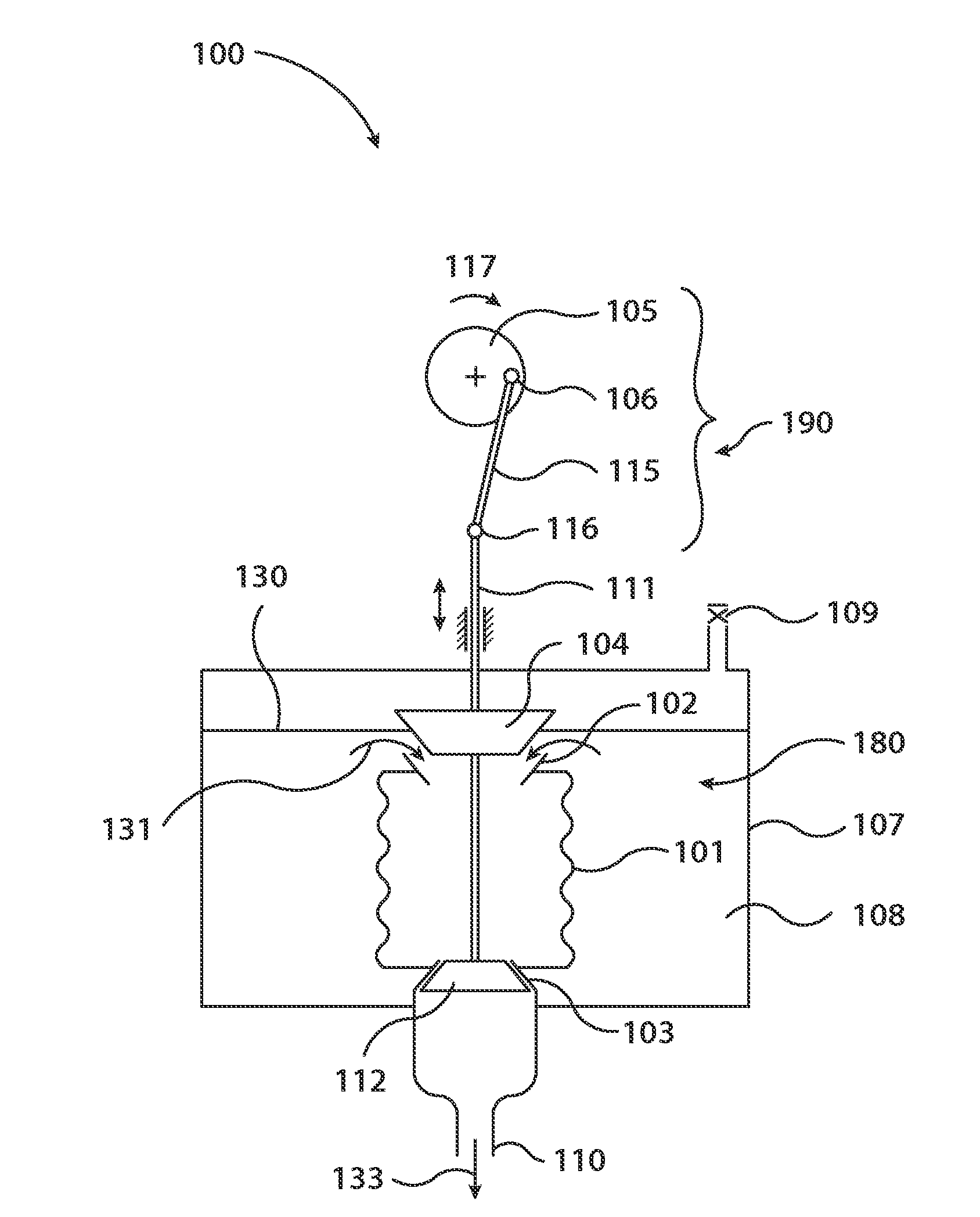
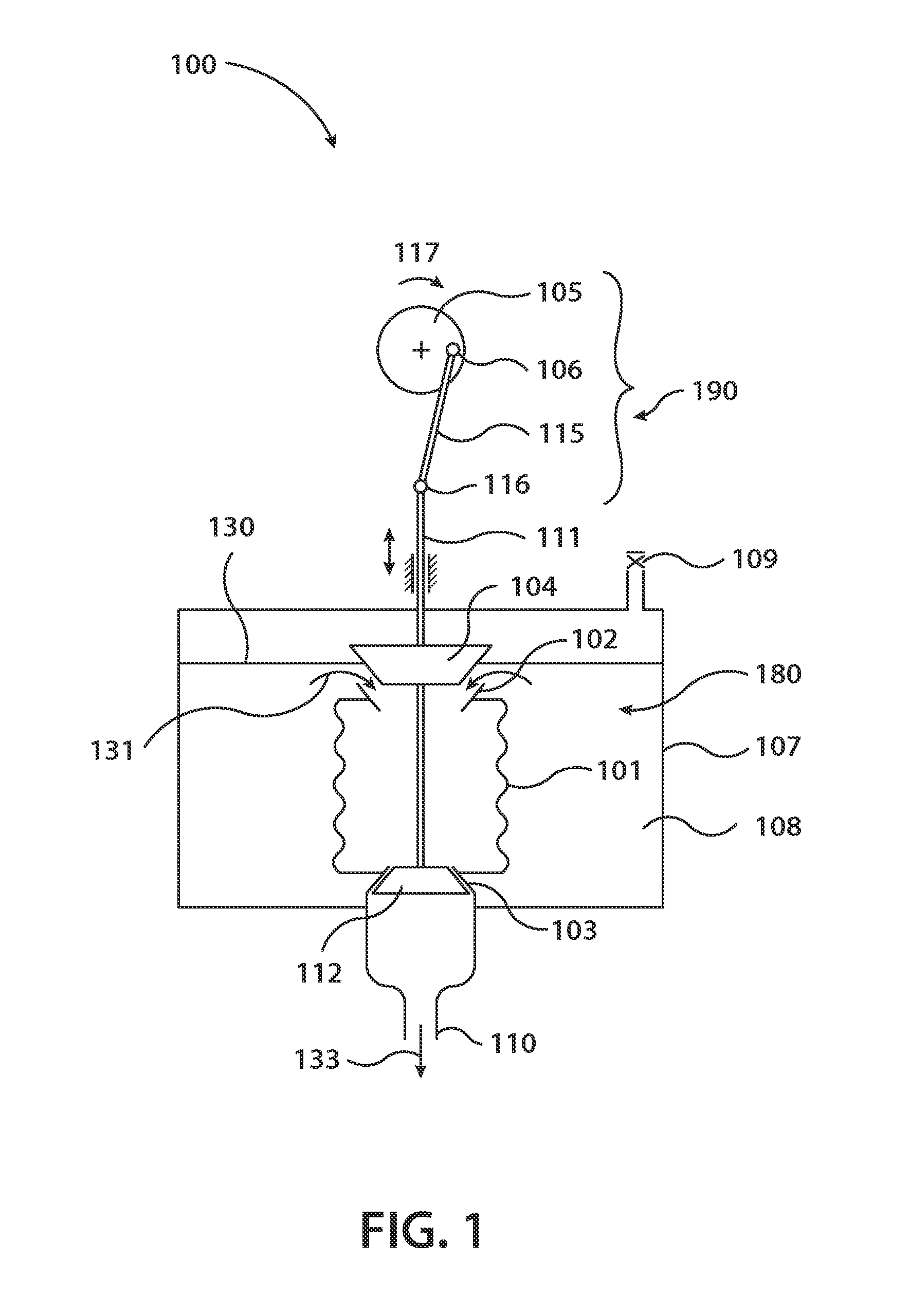
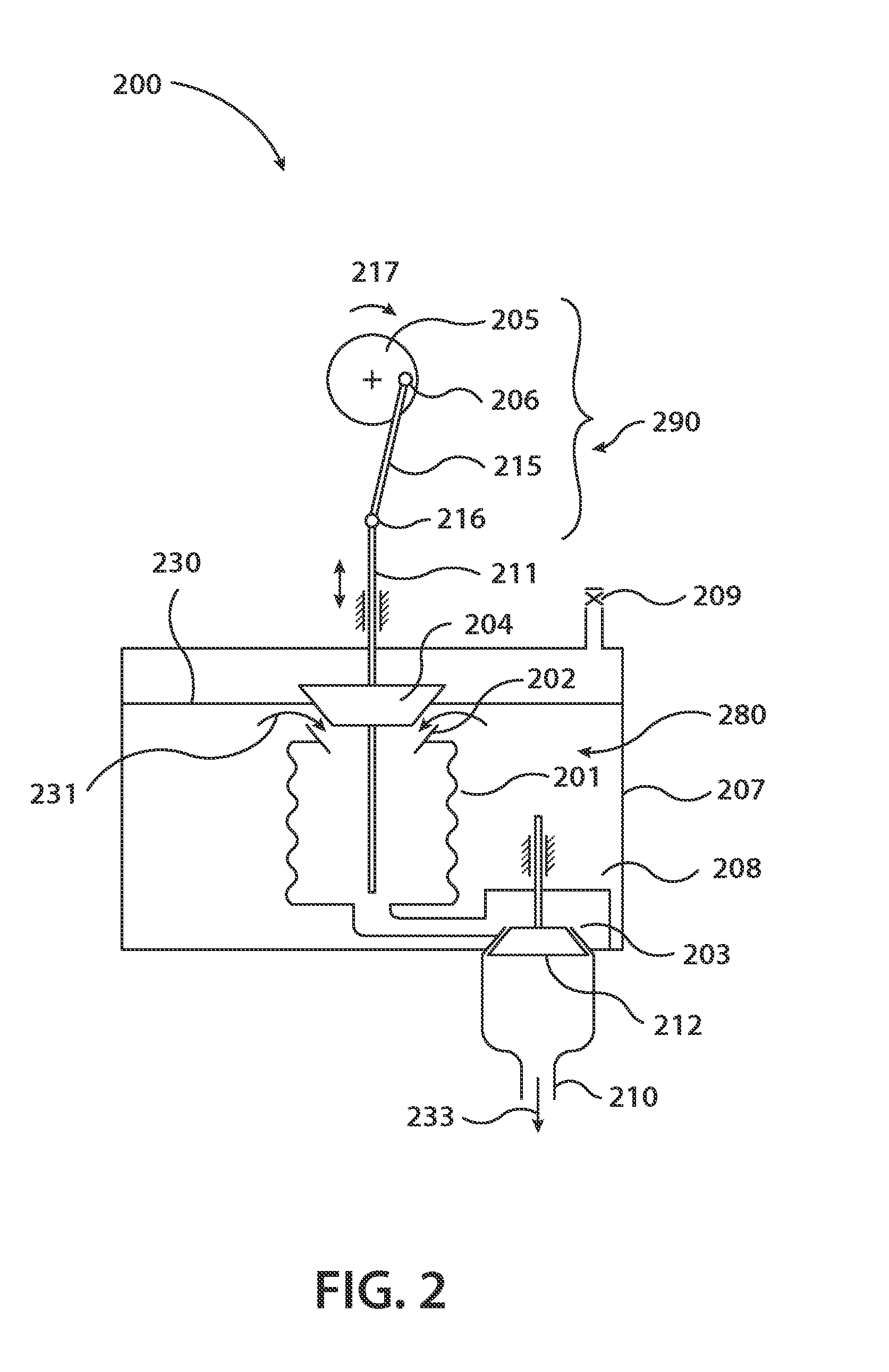
[0032]Reference will now be made in detail to embodiments of the present invention, examples of which are illustrated in the accompanying drawings, wherein like reference numerals refer to the like elements throughout. The embodiments are described below to explain the present invention by referring to the figures.

[0033]The drawings are generally not to scale. For drawing clarity, non-essential elements may have been omitted from some of the drawings.

[0034]Although the following text sets forth a detailed description of at least one embodiment or implementation, it is to be understood that the legal scope of protection of this application is defined by the words of the claims set forth at the end of this disclosure. The detailed description is to be construed as exemplary only and does not describe every possible embodiment since describing every possible embodiment would be impractical, if not impossible. Numerous alternative embodiments and / or implementations are both contemplated...


PUM


Abstract

A cryogen pump, including: a pump section that includes: a bellow with an inlet opening at a first end and an exit opening, the inlet opening in direct fluid communication with a volume of a cryogen, the exit opening at least in fluid communication with a second end of the bellow opposing the first end, a pair of plugs configured to sealingly close the opposing ends of the bellow, the pair of plugs cooperating so that when one plug sealingly closes one of the ends, the other end of the bellow is open; and a drive section configured to drive the pump section in a reciprocating manner so as to move the plugs.

Description

BACKGROUND[0001]1. Field of the Invention[0002]Embodiments of the present invention relate generally to cryogenic pumps and, more particularly, to submerged or insulated cryogenic pumps.[0003]2. Description of Related Art[0004]Handling cryogen fluid at, or slightly below its boiling temperature, which is well below room temperature, can be cumbersome due to the creation of two-phase Condition with any heat absorbed from the environment. Liquid nitrogen, as a cryogen, has additional handling difficulties associated with the Leidenfrost effect and the 700 fold volume expansion from liquid to gas.[0005]As is conventionally known, liquid nitrogen has characteristics that make it difficult to fill a volume. This difficulty is due to the Lindenfrost effect, by which a cushion of vapor results whenever the liquid comes into contact with a surface with a temperature higher than the boiling temperature.[0006]The change of pressure may be another source of difficulties related to the physical...

Claims


Application Information

Patent Timeline
Patent Type & Authority Applications(United States)
IPC IPC(8): F04B15/08
CPCF04B15/08F04B37/08F04B43/028F04B45/02F04B2015/0824B01D8/00F04B53/10F04B53/14
Inventor BERZAK, NIRSHARON, SIMONVOLOSHIN, MICHAELHILLELI, RON
Owner ICECURE MEDICAL
Why Eureka
Try Eureka