
Lock device

a technology of lock device and lock stopper, which is applied in the direction of coupling device connection, electrical apparatus, connection, etc., can solve the problems of motor-driven lock device not being able to move the lock stopper in the unlock direction to unlock the charge cable, and battery charging takes a long tim

Active Publication Date: 2014-06-19
KK TOKAI RIKA DENKI SEISAKUSHO
View PDF15 Cites 24 Cited by
  • Summary
  • Abstract
  • Description
  • Claims
  • Application Information

AI Technical Summary

Benefits of technology

The present invention provides a lock device that can be opened and closed to control access to a power port. The lock is moved between a locked position to prevent removal of the locking subject and an unlocked position to allow for removal. A transmission member is moved between a position to lock the lock and another position to unlock the lock. The lock can also be opened forcefully using a forcible unlocking mechanism that includes a movable forcible unlocking member and a holding unit. The technical effect of this invention is to provide a reliable and secure lock device for controlling access to a power port.

Problems solved by technology

The battery charging takes a long time.
However, if the actuator fails to function when the lock pin is in a lock state, the motor-driven lock device cannot move the lock stopper in the unlock direction to unlock the charge cable.

Method used


Image

  • Lock device
  • Lock device
  • Lock device

Examples


Embodiment Construction

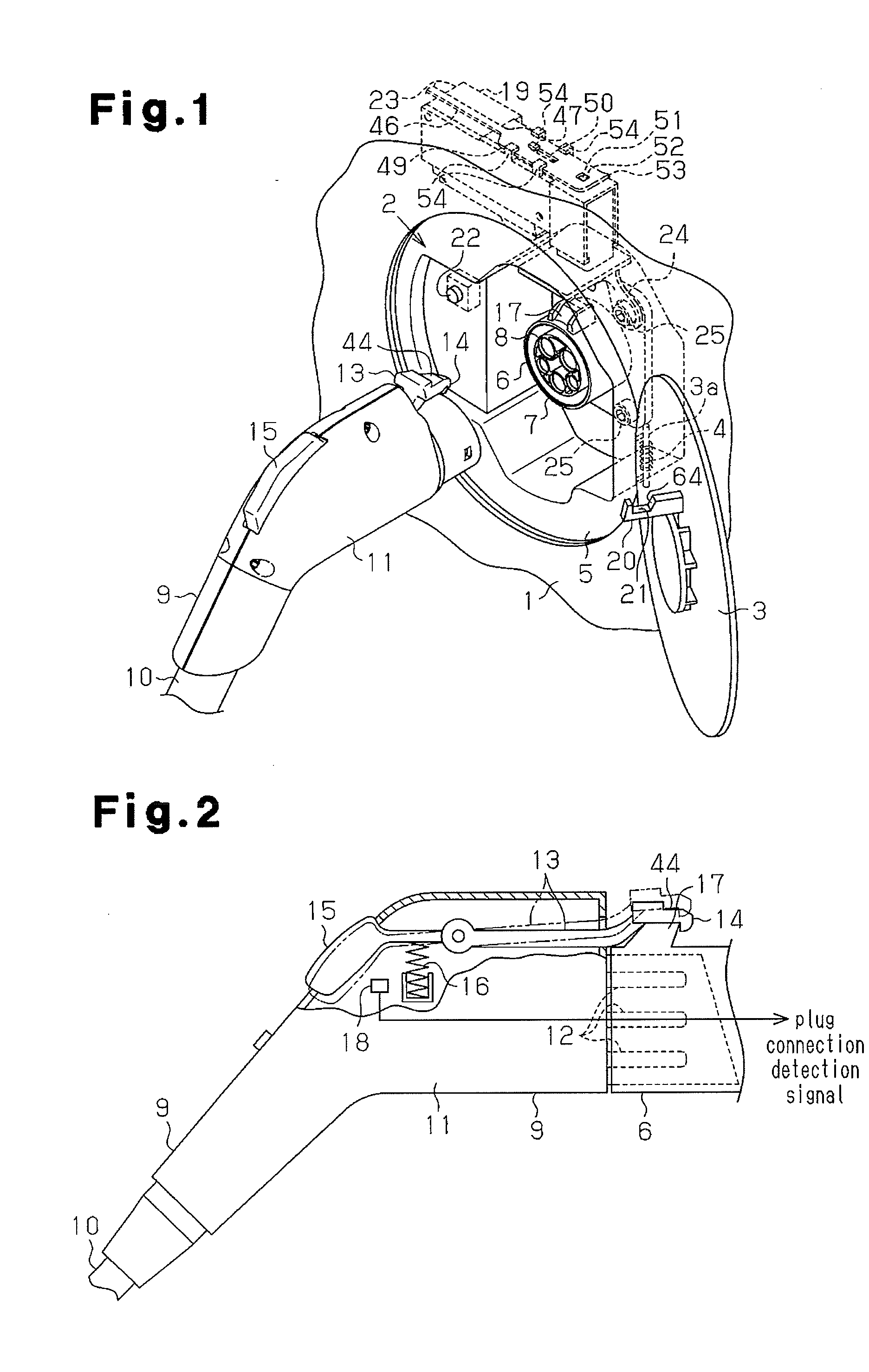
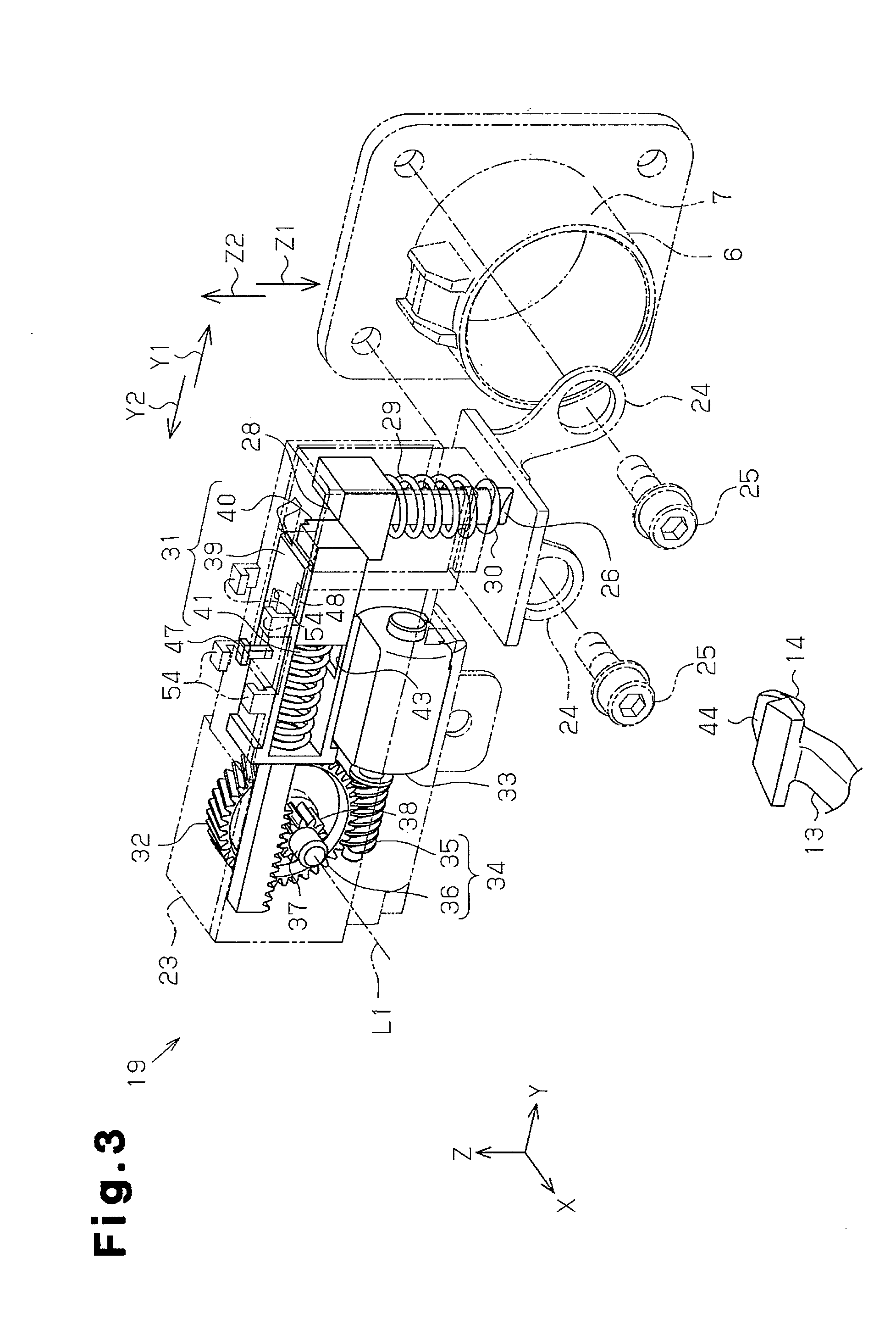
[0021]A lock device according to one embodiment of the present invention will now be described with reference to FIGS. 1 to 11.

[0022]Outline of Charge System

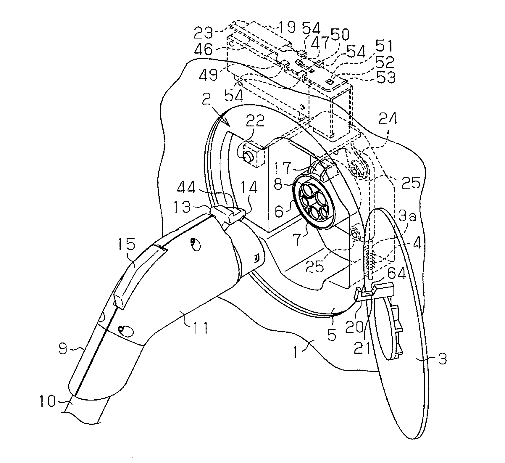
[0023]Referring to FIG. 1, a vehicle such as a plugin hybrid vehicle includes a charge system that allows for a battery (not shown) of the vehicle to be charged by an external power supply installed in a household, charging station, or the like. The body 1 of the vehicle has a side wall including a power port 2. A lid 3 opens and closes the power port 2. The lid 3 is pivotal about a shaft 3a, which extends in the vertical direction. An urging member 4, such as a torsion spring, is arranged on the shaft 3a to urge the lid to an open position. An inlet 6, which serves as a power receiving connector, is arranged at the middle of a lid box 5 in the power port 2. The inlet 6 includes a cylindrical inlet case 7, a terminal unit 8 arranged in the inlet case 7, and a catch 17 arranged on the inlet case 7. The lid 3 corresponds to a lock...


PUM


Abstract

A lock device includes a lock member moved between a lock position, at which the lock member restricts removal of a locking subject from a power port, and an unlock position, at which the lock member permits removal of the locking subject from the power port. A transmission member is moved between a first position, at which the transmission member fixes the lock member at the lock position, and a second position, at which the transmission member permits movement of the lock member to the unlock position. A forcible unlocking mechanism includes a movable forcible unlocking member, which manually moves the transmission member to the second position, and a holding unit, which holds the forcible unlocking member while permitting movement of the transmission member between the first position and the second position.

Description

CROSS-REFERENCE TO RELATED APPLICATIONS[0001]This application is based upon and claims the benefit of priority from prior Japanese Patent Application No. 2012-272497, filed on Dec. 13, 2012, the entire contents of which are incorporated herein by reference.BACKGROUND OF THE INVENTION[0002]The present invention relates to a lock device for locking and unlocking a locking subject related to a power port.[0003]Vehicles that emit less carbon dioxide, such as plugin hybrid vehicles and electric vehicles, are environment-friendly and have become popular. Such a vehicle is powered by a battery. When the battery drains after driving the vehicle over a long distance, the battery is recharged. Thus, the body of the vehicle is provided with a power port that is used to charge the battery. A charge cable of a charging facility is connected to the power port to supply power from the charging facility and charge the battery. The battery charging takes a long time. Thus, a charge cable lock device...

Claims


Application Information

Patent Timeline
Patent Type & Authority Applications(United States)
IPC IPC(8): H01R13/639
CPCH01R13/639H01R13/6275H01R13/6397H01R2201/26
Inventor KAHARA, KEIJIKATAGIRI, TOSHIHARU
Owner KK TOKAI RIKA DENKI SEISAKUSHO
Learn More