Al technical title is built by PatSnap Al team. It summarizes the technical point description of the patent document.
a piston actuator and diaphragm technology, applied in the direction of valves, mechanical devices, engine components, etc., can solve the problems of damage to the stem or internal components of the actuator, and achieve the effects of manufacturing, assembly, and significant performan
Active Publication Date: 2015-07-23
VAULT PRESSURE CONTROL LLC
View PDF9 Cites 21 Cited by
Summary
Abstract
Description
Claims
Application Information
AI Technical Summary
This helps you quickly interpret patents by identifying the three key elements:
Problems solved by technology
Method used
Benefits of technology
[0011]This application discloses embodiments of a valve actuator that is alternatively configurable for use as a diaphragm actuator, a piston actuator, or a dual or combination diaphragm and piston actuator. In various embodiments, the actuator includes modular components that are usable in one or more
Problems solved by technology
The force on the stem, however, can damage th
Method used
Image
Click on the blue label to locate the original text in one second.
Reading with bidirectional positioning of images and text.
Examples
Embodiment Construction
[0028]The system and method of the present disclosure will now be described more fully hereinafter with reference to the accompanying drawings which illustrate embodiments of the invention. The system and method if this disclosure may, however, be embodied in many different forms and should not be construed as limited to the illustrated embodiments set forth herein. Rather, these embodiments are provided so that this disclosure will be thorough and complete, and will fully convey the scope of the invention to those skilled in the art. Like numbers refer to like elements throughout, and the prime notation, if used, indicates similar elements in alternative embodiments.
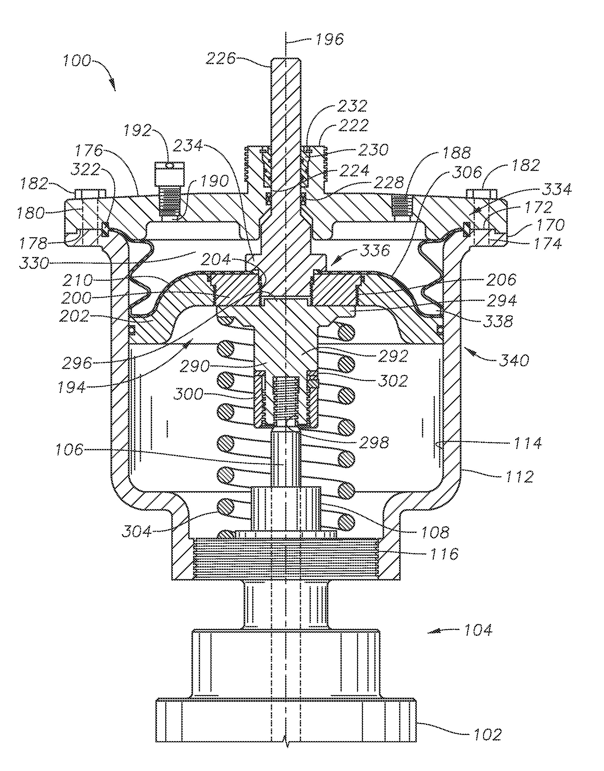
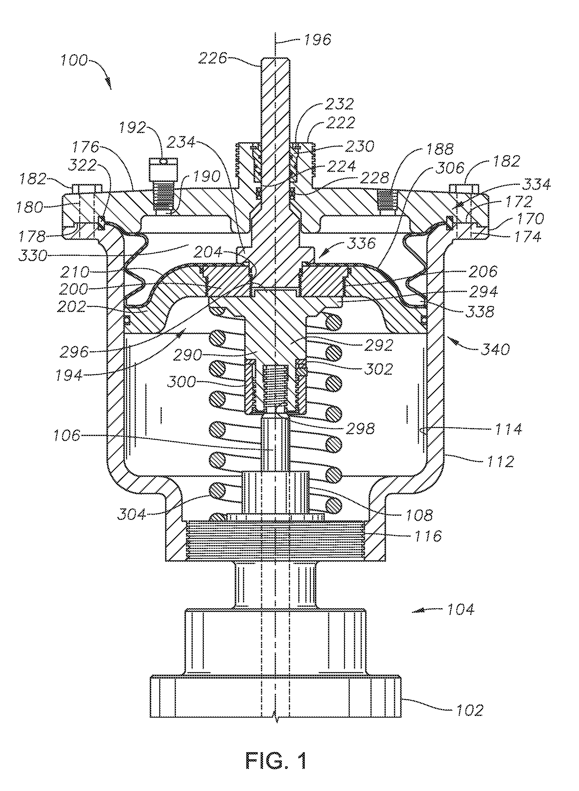
[0029]Referring to FIG. 1, actuator 100 is shown. Actuator 100 is used to open or close valve 102, to which actuator 100 is connected. As one of skill in the art will appreciate, valve 102 can be a gate valve or any other type of valve that is actuated by the extension of a linear member. Valve 102 can be, for example a...
PUM
Abstract
An apparatus for actuating a valve includes an actuator with a cap. A plate that engages the inner diameter of the actuator housing is positioned within the actuator housing. A pressure chamber is located within the actuator housing between the plate and cap. A cap seal fluidly seals the pressure chamber between the cap and the actuator housing. The pressure chamber is fluidly sealed at the plate by one of a first plate seal assembly and a second plate seal assembly. The first plate seal assembly is formed by the diaphragm being secured between a seal nut and the plate. The second plate seal assembly is formed by an outer diameter sidewall seal located between the inner diameter of the actuator housing and the outer diameter of the plate and a retainer seal located between an outer diameter of the seal nut and an inner diameter of the plate.
Description
CROSS REFERENCE TO RELATED APPLICATIONS[0001]This application claims priority to and the benefit of co-pending U.S. Provisional Application No. 62 / 049,539, titled “Non Tension Diaphragm,” filed Sep. 12, 2014, the full disclosure of which is hereby incorporated by reference herein in its entirety.[0002]This application also is a continuation-in-part of and claims priority to and the benefit of: U.S. patent application Ser. No. 13 / 679,553, now U.S. Pat. No. ______, titled “Combination Diaphragm Piston Actuator,” filed Nov. 16, 2012; U.S. patent application Ser. No. 14 / 107,589, now U.S. Pat. No. ______, titled “Non-Rising Stem Actuator,” which claims priority to and the benefit of U.S. Provisional Patent Application No. 61 / 747,753 filed Dec. 31, 2012; and U.S. patent application Ser. No. 13 / 832,884, titled “Quick Connect Valve Actuator,” which claims priority to and the benefit of U.S. Provisional Patent Application No. 61 / 747,479, titled “Quick Connect Valve Actuator,” filed Dec. 31, ...
Claims
Application Information
Patent Timeline
Application Date:The date an application was filed.
Publication Date:The date a patent or application was officially published.
First Publication Date:The earliest publication date of a patent with the same application number.
Issue Date:Publication date of the patent grant document.
PCT Entry Date:The Entry date of PCT National Phase.
Estimated Expiry Date:The statutory expiry date of a patent right according to the Patent Law, and it is the longest term of protection that the patent right can achieve without the termination of the patent right due to other reasons(Term extension factor has been taken into account ).
Invalid Date:Actual expiry date is based on effective date or publication date of legal transaction data of invalid patent.