Evaporator with cool storage function

a technology of evaporator and function, which is applied in the direction of indirect heat exchangers, refrigeration components, lighting and heating apparatus, etc., can solve the problem of sharp drop in the cooling capacity of air conditioners

Active Publication Date: 2014-06-26
MAHLE INT GMBH
View PDF28 Cites 20 Cited by
  • Summary
  • Abstract
  • Description
  • Claims
  • Application Information

AI Technical Summary

Benefits of technology

[0010]According to one aspect of the present invention, an evaporator with a cool storage function includes a plurality of flat refrigerant flow tubes, outer fins, at least one cool storage material container, and an inner fin. The plurality of flat refrigerant flow tubes have a longitudinal direction and a width direction which is perpendicular to the longitudinal direction and along which air is to pass. The plurality of flat refrigerant flow tubes are disposed in parallel and spaced apart from one another in a thickness direction of the plurality of refrigerant flow tubes to form spaces among the plurality of flat refrigerant flow tubes. The thickness direction is perpendicular to the longitudinal direction and the width direction. The outer fins are disposed in a first part of the spaces and joined to the plurality of refrigerant flow tubes. The cool storage material container contains a cool storage material and is disposed in a second part of the spaces other than the first part. The inner fin is disposed within the cool storage material container and has crest portions extending along the longitudinal direction, trough portions extending along the longitudinal direction, and connection portions connecting the crest portions and the trough portions.
[0056]In the evaporator with a cool storage function according to the embodiment, the cool storage material is in contact with the inner fin at all times during cool storage periods during which cool is stored in the cool storage material and during cool release periods during which the cool stored in the cool storage material is released. Therefore, the evaporator has an improved cool storage efficiency and an improved cool release efficiency.
[0026]As shown in FIGS. 1 and 2, an evaporator with a cool storage function 1 includes a first header tank 2 and a second header tank 3 formed of aluminum and disposed apart from each other in the vertical direction such that they extend in the left-right direction; and a heat exchange core section 4 provided between the two header tanks 2 and 3.
[0058]In the evaporator with a cool storage function according to the embodiment, when the cool storage material is charged into the cool storage material container, for example, through a cool storage material charging inlet provided on the outward projecting portion, the cool storage material flows through the through-holes formed in the connection portions of the corrugated inner fin and fills the entire space within the cool storage material container.
[0060]In the evaporator with a cool storage function according to the embodiment, the inner fin within the cool storage material container has an integrally formed extension portion which extends to the outward projecting portion. Therefore, even in the case where the cool storage material container has a container main body portion joined to the corresponding refrigerant flow tubes, and an outward projecting portion which is continuous with the leeward edge or windward edge of the container main body portion such that the outward projecting portion projects beyond the refrigerant flow tubes in the air-passing direction, the movement of the liquid-phase cool storage material between the container main body portion and the outward projecting portion of the cool storage material container can be restricted effectively.
[0028]In the heat exchange core section 4, a plurality of flat refrigerant flow tubes 12 which extend in the vertical direction, whose width direction coincides with the air-passing direction (the front-rear direction), and which are formed of aluminum extrudate are disposed in parallel such that they are spaced from one another in the left-right direction (the thickness direction of the refrigerant flow tubes 12). In the present embodiment, a plurality of pairs 13 each composed of two refrigerant flow tubes 12 spaced from each other in the front-rear direction are disposed at predetermined intervals in the left-right direction. A clearance 14 is formed between adjacent two of the pairs 13 each composed of the front and rear refrigerant flow tubes 12. An upper end portion of each front refrigerant flow tube 12 is connected to the leeward upper header section 5, and a lower end portion of each front refrigerant flow tube 12 is connected to the leeward lower header section 9. Similarly, an upper end portion of each rear refrigerant flow tube 12 is connected to the windward upper header section 6, and a lower end portion of each rear refrigerant flow tube 12 is connected to the windward lower header section 11.
[0062]In the evaporator with a cool storage function according to the embodiment, the amount of the cool storage material present in the outward projecting portion which is not in direct contact with the refrigerant flow tubes can be reduced, whereby a portion of all the cool storage material charged into the cool storage material container, which portion is not cooled effectively, can be reduced in amount. Namely, the strength of the cool storage material container and the cool storage material charging ratio (the ratio of the volume of the charged cool storage material to the volume of the internal space of the cool storage material container) are designed such that the cool storage material container does not break within the ordinary use environment temperature rang (e.g., within a range of −40° C. to 90° C.) even when the density of the cool storage material in the liquid phase changes and the air remaining in the cool storage material container thermally expands with a resultant increases in the internal pressure. Since such a cool storage material charging ratio is of course less than 100%, a space which is not occupied by the cool storage material is present near the upper end of the cool storage material container. Therefore, the entire interior of the outward projecting portion provided over a predetermined length from the upper end of the leeward edge or windward edge of the container main body portion is not filled with the cool storage material. As a result, the amount of the cool storage material not cooled effectively (of all the cool storage material charged into the cool storage material container) can be reduced.
[0035]A paraffin-based latent heat storage material whose freezing is adjusted to 5° C. to 10° C. is used as a cool storage material which is charged into each cool storage material container 15. Specifically, pentadecane, tetradecane, or the like is used. Preferably, a cool storage material charging ratio (the ratio of the volume of the charged cool storage material to the volume of the internal space of the cool storage material container 15) is set to 70% to 90%. The upper end of the inner fin 24 is preferably located above the upper end P of the cool storage material charged into the cool storage material container 15. In this case, the cool storage material is in contact with the inner fin 24 at all times during cool storage periods during which cool is stored in the cool storage material and during cool release periods during which the cool stored in the cool storage material is released.
[0035]A paraffin-based latent heat storage material whose freezing is adjusted to 5° C. to 10° C. is used as a cool storage material which is charged into each cool storage material container 15. Specifically, pentadecane, tetradecane, or the like is used. Preferably, a cool storage material charging ratio (the ratio of the volume of the charged cool storage material to the volume of the internal space of the cool storage material container 15) is set to 70% to 90%. The upper end of the inner fin 24 is preferably located above the upper end P of the cool storage material charged into the cool storage material container 15. In this case, the cool storage material is in contact with the inner fin 24 at all times during cool storage periods during which cool is stored in the cool storage material and during cool release periods during which the cool stored in the cool storage material is released.

Problems solved by technology

However, an ordinary car air conditioner has a problem in that, when an engine of an automobile in which the air conditioner is mounted is stopped, a compressor driven by the engine is stopped, and supply of refrigerant to an evaporator stops, whereby the cooling capacity of the air conditioner drops sharply.

Method used


Image

  • Evaporator with cool storage function
  • Evaporator with cool storage function
  • Evaporator with cool storage function

Examples


Embodiment Construction

[0021]An embodiment of the present invention will next be described with reference to the drawings.

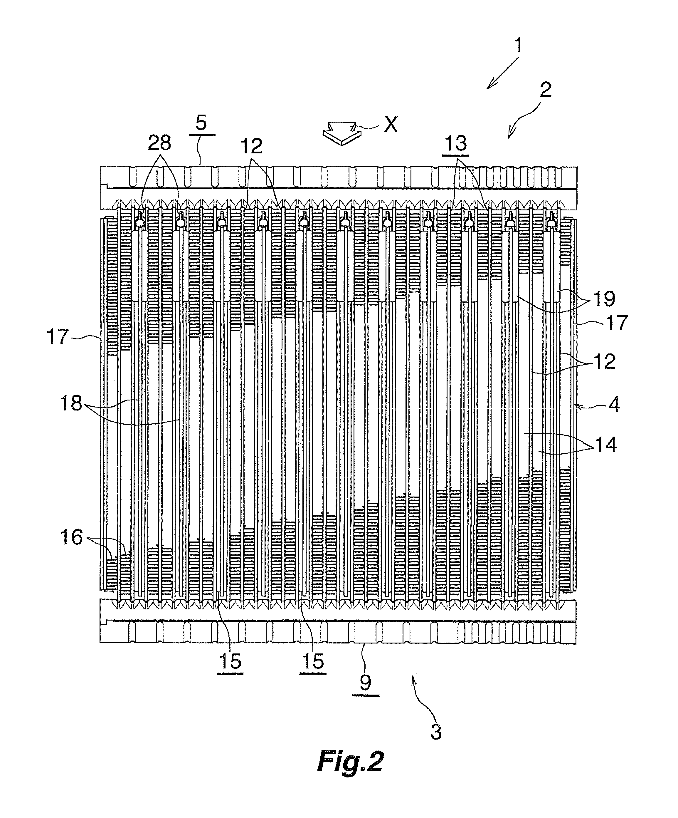
[0022]In the present specification, the upper, lower, left-hand, and right-hand sides of FIG. 2 will be referred to as “upper,”“lower,”“left, and “right,” respectively.

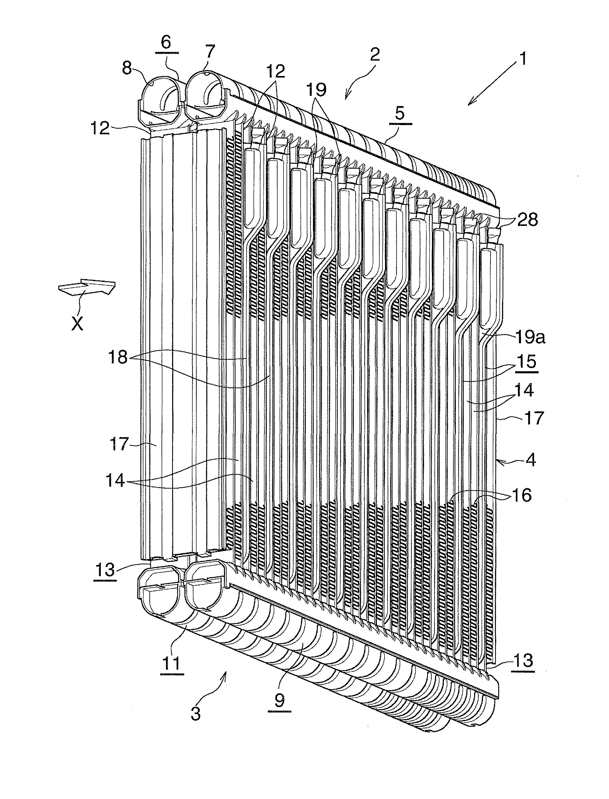
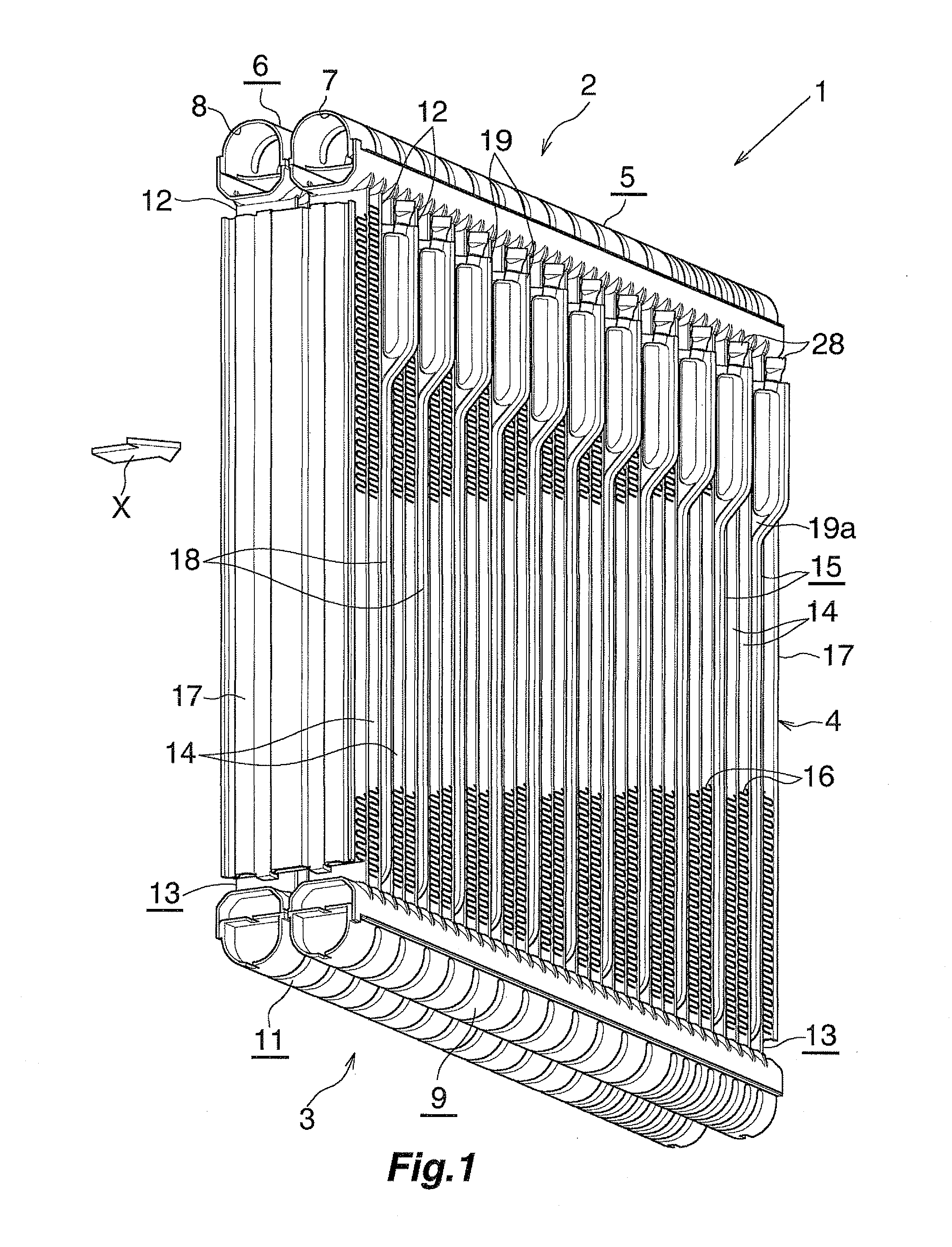
[0023]In the following description, the downstream side with respect to an air-passing direction (a direction represented by arrow X in FIGS. 1 through 3) will be referred to as the “front,” and the opposite side as the “rear.” Accordingly, the upper, lower, left-hand, and right-hand sides of an evaporator as viewed rearward from the front side correspond to the upper, lower, left-hand, and right-hand sides of FIG. 2.

[0024]Furthermore, the term “aluminum” as used in the following description encompasses aluminum alloys in addition to pure aluminum.

[0025]FIGS. 1 and 2 show the overall configuration of an evaporator with a cool storage function according to an embodiment of the present invention, and FIGS. 3 to 7 show the ...


PUM


Abstract

An evaporator with a cool storage function includes a plurality of flat refrigerant flow tubes which spaced apart from one another in a thickness direction of the plurality of refrigerant flow tubes to form spaces among the plurality of flat refrigerant flow tubes. The outer fins are disposed in a first part of the spaces and joined to the plurality of refrigerant flow tubes. The cool storage material container contains a cool storage material and is disposed in a second part of the spaces other than the first part. The inner fin is disposed within the cool storage material container and has crest portions extending along the longitudinal direction, trough portions extending along the longitudinal direction, and connection portions connecting the crest portions and the trough portions.

Description

CROSS-REFERENCE TO RELATED APPLICATIONS[0001]The present application claims priority under 35 U. S. C. §119 to Japanese Patent Application No. 2012-280861, filed Dec. 25, 2012. The contents of this application are incorporated herein by reference in their entirety.BACKGROUND OF THE INVENTION[0002]1. Field of the Invention[0003]The present invention relates to an evaporator with a cool storage function.[0004]2. Discussion of the Background[0005]In recent years, in order to protect the environment and improve fuel consumption of automobiles, there has been proposed an automobile designed to automatically stop the engine when the automobile stops, for example, to wait for a traffic light to change.[0006]However, an ordinary car air conditioner has a problem in that, when an engine of an automobile in which the air conditioner is mounted is stopped, a compressor driven by the engine is stopped, and supply of refrigerant to an evaporator stops, whereby the cooling capacity of the air con...

Claims


Application Information

Patent Timeline
Patent Type & Authority Applications(United States)
IPC IPC(8): F25B39/02
CPCF25B39/022F25B2400/24F28D1/0333F28D1/05391F28D20/02F28D2021/0085F28D2020/0013Y02E60/14F25B39/02
Inventor HIRAYAMA, TAKASHIKAMOSHIDA, OSAMU
Owner MAHLE INT GMBH
Why Eureka
Try Eureka