Testing method of bending stress and testing apparatus thereof

a testing method and bending stress technology, applied in the field of testing methods and testing apparatuses, can solve the problems of reducing the bending strength of thinned substrates, reducing the structure strength of substrates accordingly, and forming the required size of substrates through cutting, so as to achieve accurate testing results and simple, fast and effective manners

Active Publication Date: 2014-06-26
IND TECH RES INST
View PDF1 Cites 9 Cited by
  • Summary
  • Abstract
  • Description
  • Claims
  • Application Information

AI Technical Summary

Benefits of technology

This patent describes a method and apparatus for testing bending stress on a material. The method involves building a model of the material's stress distribution and then bending a testing sample of the material until it breaks at a specific point. The distance between the two ends of the sample is measured, and the maximum or breaking point principle stress value is calculated based on this information. The apparatus includes two fixtures that move relative to each other to apply force to the sample's ends. The technical effects include a simplified and efficient method for testing bending stress and a specialized apparatus for carrying out this testing.

Problems solved by technology

However, a bending strength of the thinned substrate is decreased, and a structure strength of the substrate is accordingly decreased.
Moreover, in the conventional technique, a required size of the substrate is formed through cutting.
However, the substrate generally includes a fragile material such as glass, silicon substrate and ceramics, etc., and when the substrate is cut, a fracture surface is liable to have defects.
If a cutting fracture surface of the substrate has small defects such as scars, cracks or foreign body, etc., when the substrate is bended, a problem of stress concentration is occurred around the defect, which may cause damage of the substrate.

Method used


Image

  • Testing method of bending stress and testing apparatus thereof
  • Testing method of bending stress and testing apparatus thereof
  • Testing method of bending stress and testing apparatus thereof

Examples


Embodiment Construction

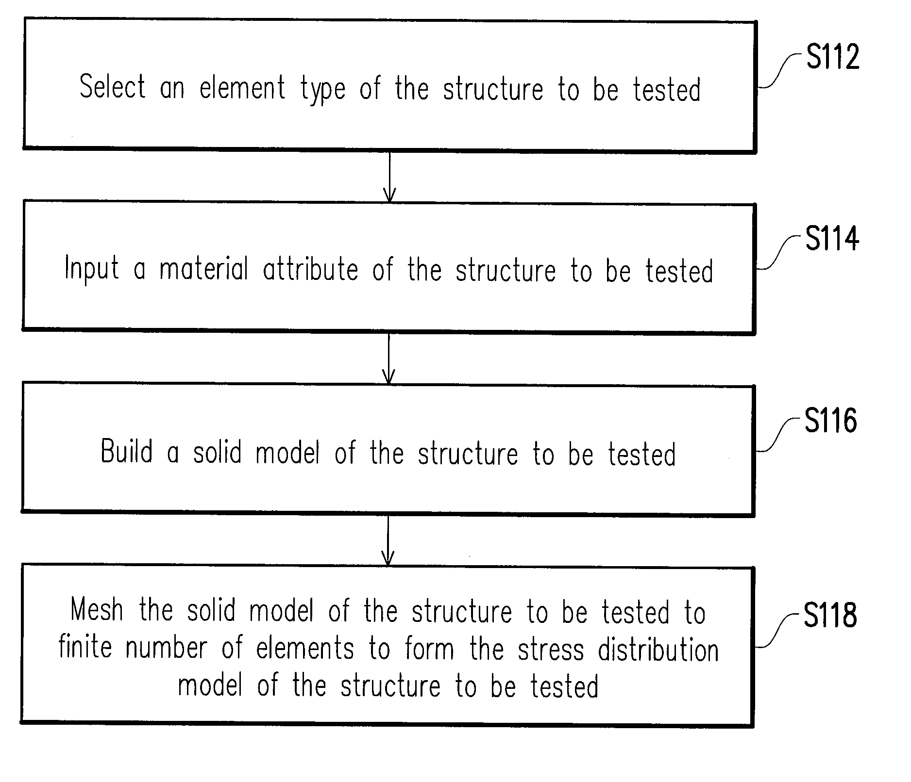
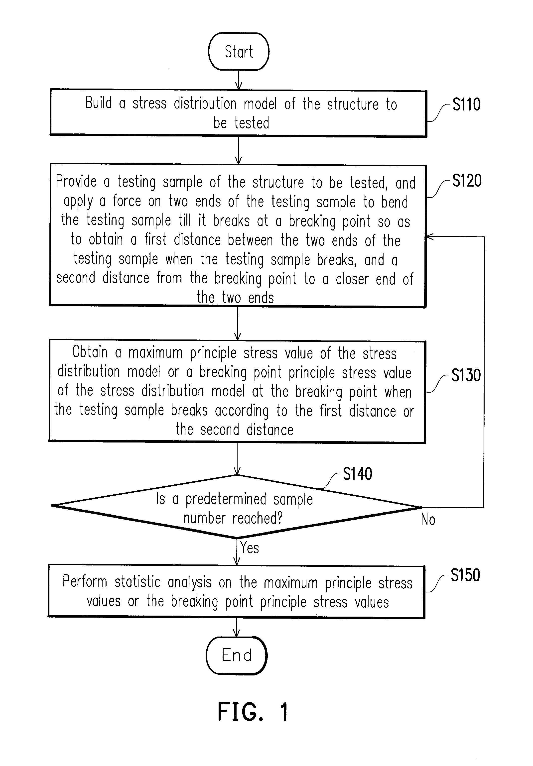
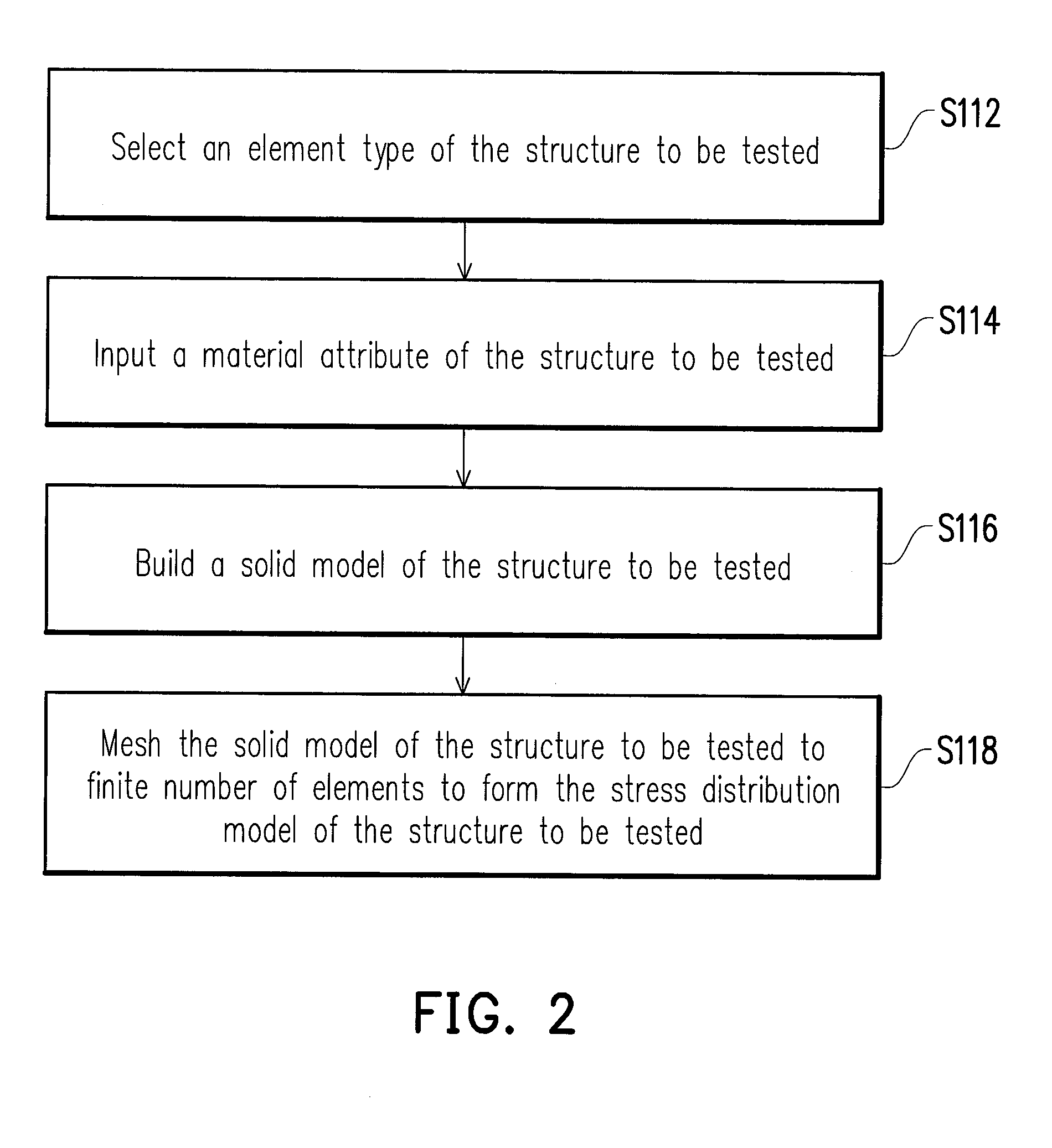
[0018]FIG. 1 is a flowchart of a testing method of bending stress according to an embodiment of the disclosure. FIG. 2 is a flowchart of finite element analysis according to an embodiment of the disclosure. Referring to FIG. 1, the testing method of bending stress of the present embodiment is adapted to test a structure to be tested, and a material of the structure to be tested is for example, a fragile material. The testing method of bending stress includes following steps. First, in step S110, a stress distribution model of the structure to be tested is built. In the present embodiment, a method of building the stress distribution model includes finite element analysis (FEA). In detail, steps of the FEA are shown in the flowchart of FIG. 2, first, in step S112, an element type of the structure to be tested is selected. In the present embodiment, the element type of the structure to be tested is set to three-dimensional (3D) solid, shell or 2D element. Then, in step S114, a materia...


PUM


Abstract

A testing method of bending stress and a testing apparatus thereof are provided. The method includes the following steps. A stress distribution model of a structure to be tested is built. Next, a testing sample of the structure to be tested is provided, and a force is applied on two ends of the testing sample to bend the testing sample till it breaks at a breaking point, so as to obtain a first distance between the two ends of the testing sample when the testing sample breaks, or a second distance from the breaking point to a closer end of the two ends. Next, a maximum principle stress value of the stress distribution model or a break point principle stress value at the breaking point of the stress distribution model is obtained according to the first distance or the second distance.

Description

CROSS-REFERENCE TO RELATED APPLICATION[0001]This application claims the priority benefit of Taiwan application serial no. 101149169, filed on Dec. 21, 2012. The entirety of the above-mentioned patent application is hereby incorporated by reference herein and made a part of this specification.BACKGROUND[0002]1. Technical Field[0003]The disclosure relates to a testing method and a testing apparatus. Particularly, the disclosure relates to a testing method of bending stress and a testing apparatus thereof.[0004]2. Related Art[0005]In recent years, along with quick development of electronic technology, and emerging of high-tech electronics industries, more user-friendly and more powerful electronic products are quickly developed and have design features of lightness, slimness, shortness and smallness. In a convention technique, substrate thinning is a method of decreasing a weight and thickness of an electronic device. However, a bending strength of the thinned substrate is decreased, a...

Claims


Application Information

Patent Timeline
IPC IPC(8): G01N3/20
CPCG01N3/20G01N2203/0282G01N2203/0435
Inventor SHEN, CHIH-MINGHUANG, GUO-SHING
Owner IND TECH RES INST
Why Eureka
Try Eureka