Rail guide for a longitudinal adjustment of a motor vehicle seat and method for producing such a rail guide

a technology for longitudinal adjustment and motor vehicles, which is applied in the direction of moving seats, machine supports, other domestic objects, etc., can solve the problems of only moving seats in linear fashion, no other movement is possible, and certain expenditur

Active Publication Date: 2014-06-26
KEIPER SEATING MECHANISMS CO LTD
View PDF8 Cites 8 Cited by
  • Summary
  • Abstract
  • Description
  • Claims
  • Application Information

AI Technical Summary

Benefits of technology

[0023]Finally, the invention also relates to a motor vehicle equipped with a rail guide or a motor vehicle seat as described above. In this motor vehicle, the rail guide is disposed in such a way that, in the rearmost position of the longitudinal adjustment mechanism, the motor vehicle seat, particularly its backrest, is inclined rearwards at an angle of 10° to 15° measured from the vertical, and in the foremost position is inclined rearwards at an angle of 5° to 10°, again measured from the vertical, with the change of angle between these two positions being at least 4°, preferably 6°. In this way, the desired adjustment positions are obtained directly by means of the rail guide without any additional setting devices being required. This results in a significant advantage with regard to cost and weight.
[0024]In the motor vehicle seat, the seat region is preferably rigidly connected to the rails. Preferably, no setting devices are provided between the seat rail and the seat region. This saves the components of a seat height adjustment mechanism and / or seat inclination adjustment mechanism which are usually provided. These components include, for example, a seat-lifting spring that has to have a certain spring force, which means a considerable amount of weight; joint arms and setting devices, for example wobble joint fittings, are saved.

Problems solved by technology

In the case of straight rails, there is, however, the disadvantage that the seat is only moved in a linear manner in space when adjusted, but that no other movements are possible.
However, if such a joint is provided, this means a certain expenditure.
They offer good comfort but also require added expenditure.
In principle, these and any other additional adjustment device mean added weight and expenditure as regards material and assembly.

Method used


Image

  • Rail guide for a longitudinal adjustment of a motor vehicle seat and method for producing such a rail guide
  • Rail guide for a longitudinal adjustment of a motor vehicle seat and method for producing such a rail guide
  • Rail guide for a longitudinal adjustment of a motor vehicle seat and method for producing such a rail guide

Examples


Embodiment Construction

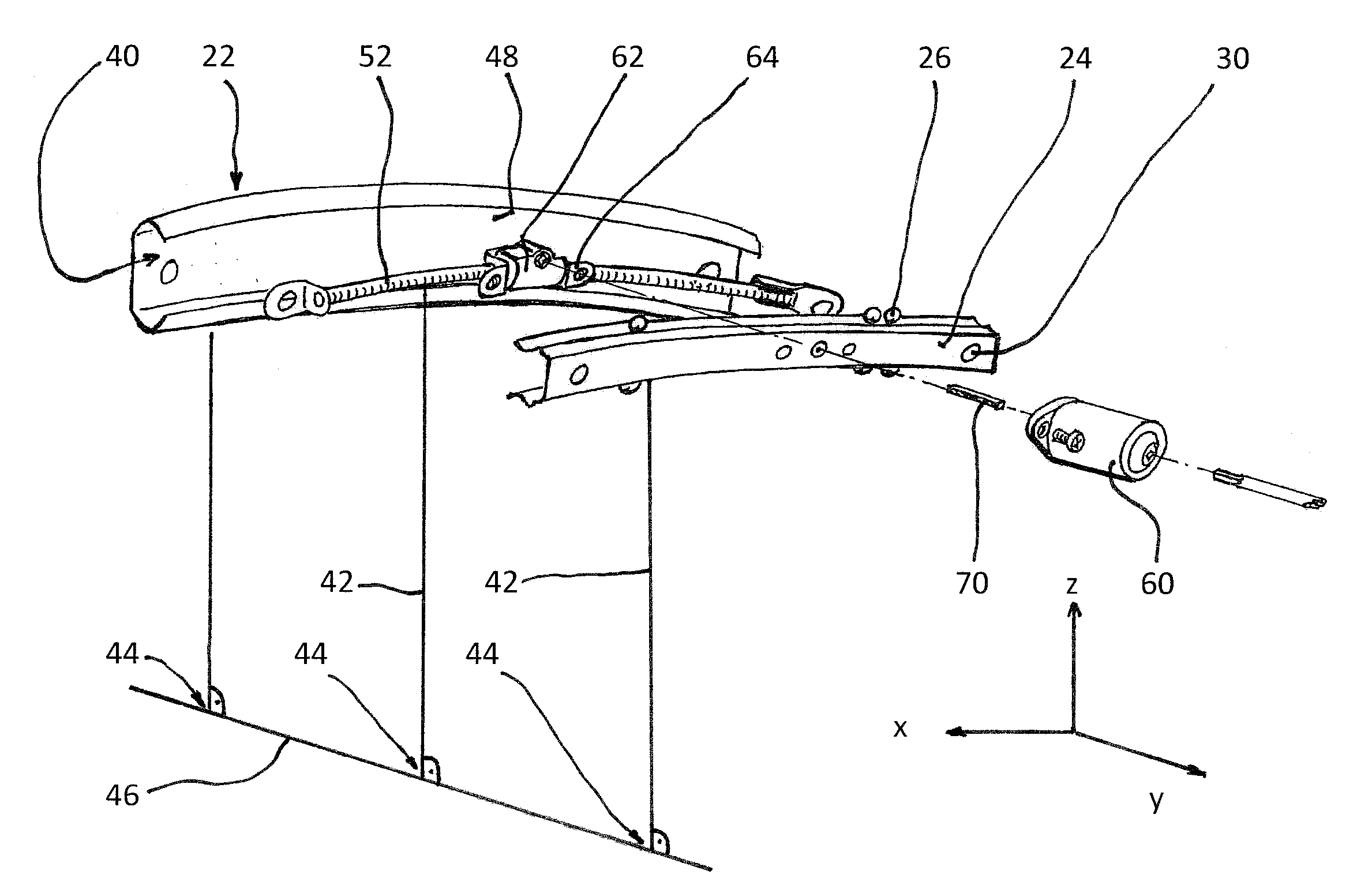
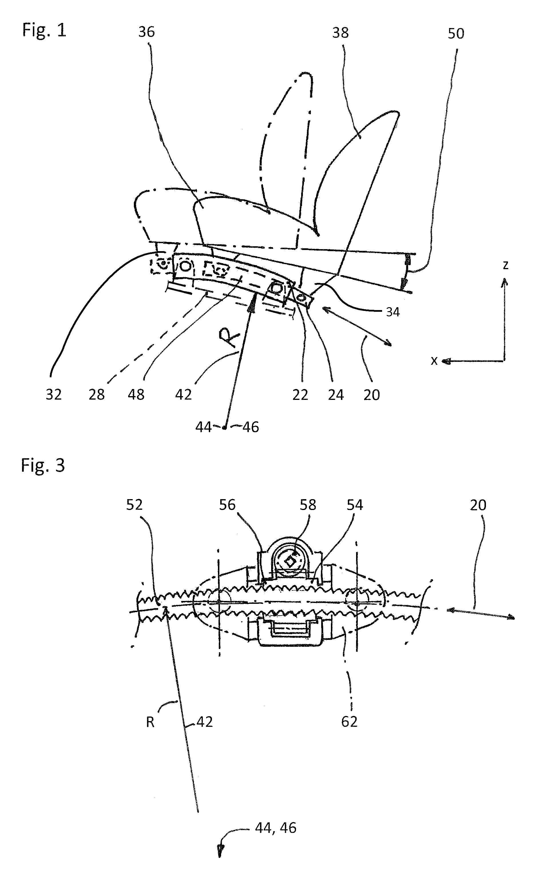
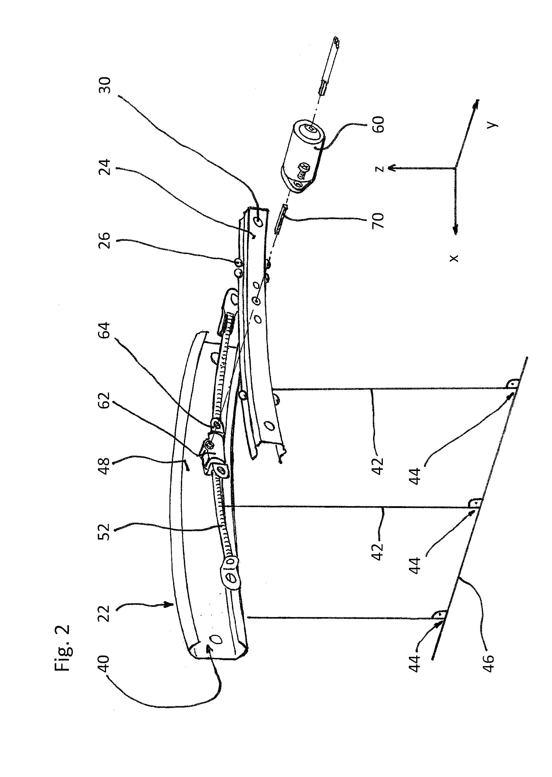
[0042]Referring to the drawings in particular, the motor vehicle seat shown in FIG. 1 is shown in two different extreme positions, namely in continuous lines in a rearmost position and in dash-dotted lines in a foremost position. Both positions are reached along a displacement path 20 extending on an arc of a circle.

[0043]In the known manner, the motor vehicle seat has at least one pair of rails comprising a floor rail 22, a seat rail 24 and guiding means 26. In the exemplary embodiment shown, two rail guides disposed parallel to each other are provided. In the exemplary embodiment, they are constructionally identical. The guiding means 26 are configured as balls; other configurations are possible. The floor rail 22 is substantially C-shaped. It is formed as a grasping rail. It comprises means for fastening to a floor assembly 28 of a motor vehicle that is otherwise not shown in more detail. The seat rail 24 is a rail which is grasped; it is also substantially C-shaped. It comprises...


PUM

PropertyMeasurementUnit
angleaaaaaaaaaa
angleaaaaaaaaaa
angleaaaaaaaaaa

Abstract

A rail guide that has at least one rail pair consisting of a floor rail (22) and a seat rail (24). The seat rail (24) has means (30) for fastening a seat frame to be arranged above the rail pair. The rails can be moved relative to each other in a longitudinal direction along a movement path (20). The floor rail (22) and the seat rail (24) are curved by the same circular radius of curvature (42) that ranges between 1,500 and 3,000 mm, in particular between 1,800 and 2,500 mm. The center point of curvature (44) is on the side of the rail pair facing away from the seat frame. The rail guide is a longitudinal adjustment device having a stationary spindle (52) and an associated spindle nut (54) that is longitudinally movable thereon, the spindle (52) being curved at the same circular radius of curvature (42). Also disclosed is a suitable method for producing said curved rails by means of at least one stamping mold (68) or by means of bending strips (96).

Description

CROSS REFERENCE TO RELATED APPLICATIONS[0001]This application is a United States National Phase Application of International Application PCT / EP2012 / 065064 filed Aug. 1, 2012 and claims the benefit of priority under 35 U.S.C. §119 of German Patent Application 10 2011 080 221.5 filed Aug. 1, 2011, the entire contents of which are incorporated herein by reference.FIELD OF THE INVENTION[0002]The invention relates to a rail guide for a longitudinal adjustment mechanism of a motor vehicle seat with at least one pair of rails, which comprises a floor rail, a seat rail and guiding means disposed between these two rails, the rails of the pair of rails being displaceable relative to each other along a displacement path in a longitudinal direction, which is substantially parallel to an x-axis, and the seat rail comprising means for fastening a seat frame to be disposed above the pair of rails.BACKGROUND OF THE INVENTION[0003]Such a rail guide is known from DE 42 38 486 A1, for example FIG. 2 o...

Claims


Application Information

Patent Timeline
Patent Type & Authority Applications(United States)
IPC IPC(8): B60N2/075B60N2/06
CPCB60N2/06B60N2/075B21D19/08B21D22/02B21D53/88B60N2/067B60N2/0715B60N2/0745B60N2/0747B60N2/1695B60N2/1832B60N2/1853B60N2/02246B21D5/01B60N2/07B60N2/18
Inventor BECKER, BURCKHARDKIENKE, INGOBALIN, ALEXANDERSEIBOLD, KURT
Owner KEIPER SEATING MECHANISMS CO LTD
Why Eureka
Try Eureka