
Color control of dynamic lighting

a dynamic lighting and color control technology, applied in the direction of electric variable regulation, process and machine control, instruments, etc., can solve the problems of time-consuming process, consumer needs to construct a very complex system, complex procedure, etc., and achieve the effect of easy construction/assembly and comparison

Inactive Publication Date: 2014-06-26
KRAUSE CHRISTIAN
View PDF1 Cites 2 Cited by
  • Summary
  • Abstract
  • Description
  • Claims
  • Application Information

AI Technical Summary

Benefits of technology

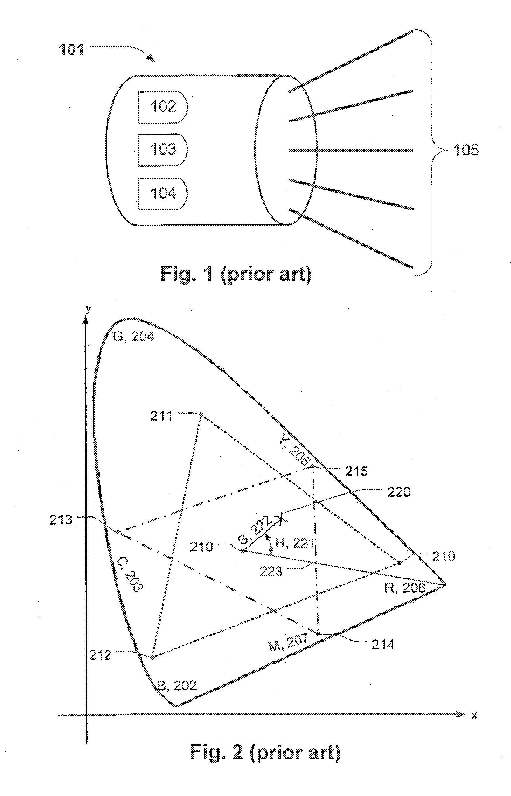
[0010]In another embodiment the method comprises the step of obtaining color parameters describing the color of said first and second source colors of said first and second lighting fixtures as a source position on a color map and generating said color gamut using said color parameters. Hereby a simple and fast method of adjusting the fixture color of lighting fixtures is provided. The color parameter describes the position of the source colors of each lighting fixtures in a color, etc. The color parameters could for instance be described by (x,y,z) coordinates, (hue, saturation) parameters or any other parameter capable of defining a position in a color map. The color gamut could by defined from the color parameter. The color parameters could be obtained, for instance, by entering the color parameters manually or automatically when the lighting fixtures are connected e.g. through a network. The method makes it possible to connect a multiple number of lighting fixtures and to easily adjust the fixture color of each lighting fixture to a target color since the fixture color of each lighting fixture could be adjusted to the target color by using the color parameters and color gamut of the individual lighting fixtures.
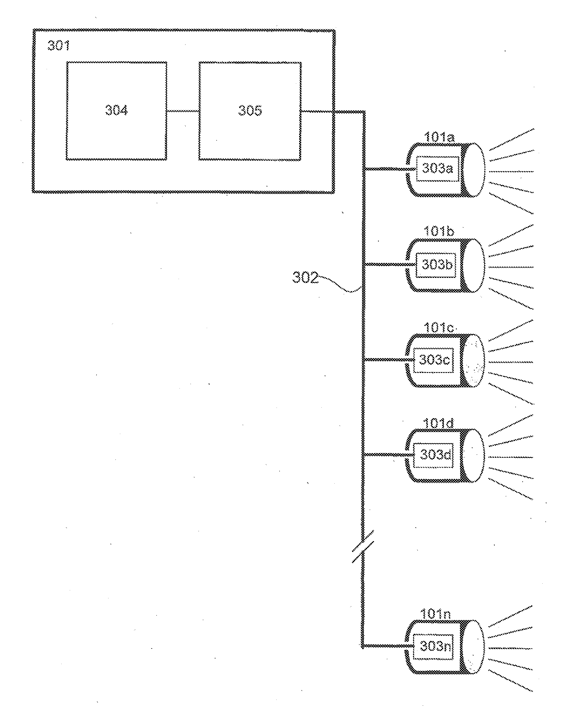
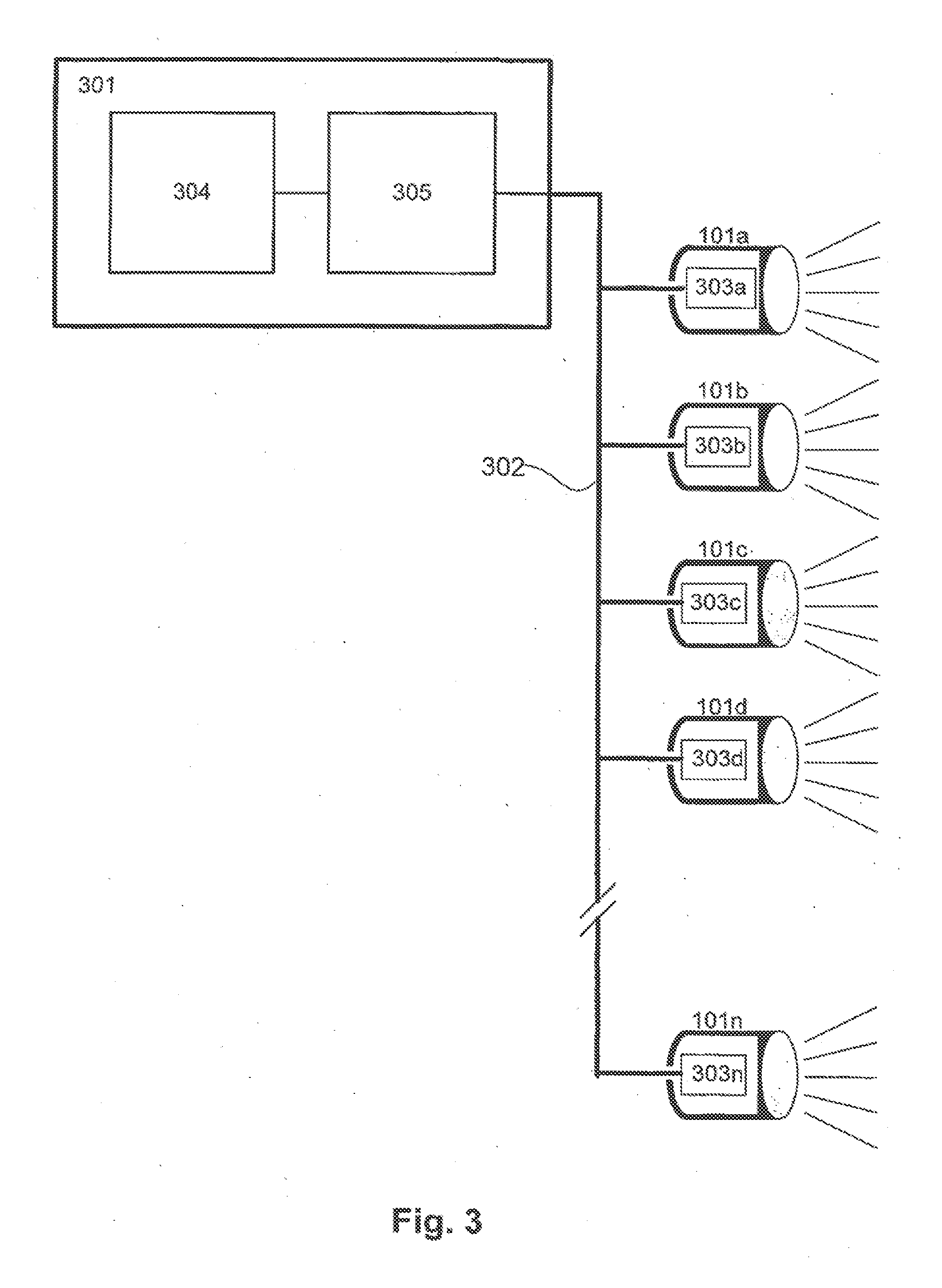
[0026]In another embodiment of the lighting system said means for adjusting said fixture color of said lighting fixtures comprised by said light fixture are adapted to adjust said fixture color through said network. Hereby a lighting system could easily be contrasted by a user without the user having to worry about controlling the individual lighting fixtures.

Problems solved by technology

Furthermore, a large number of vendors producing dynamic lighting fixtures exists, and the consumer therefore has the possibility of choosing between a large number of different dynamic lighting fixtures.
This is a very complex procedure due to a high number of different light sources, different color parameters and different color mixing systems.
Typically the consumer needs to construct a very complex system in order to combine / integrate a multiple number of dynamic lighting systems.
This is a very time consuming process because it requires measuring of the spectral distribution of each light source, complex programming and detailed knowledge of system specifications of each dynamic lighting system in order to make sure that each dynamic system would be correctly controlled.
One problem when combining different dynamic lighting fixtures is to ensure that the chosen color would appear identical on the different dynamic lighting fixtures.
This is a very time consuming process, especially when a consumer wants to combine different dynamic lighting fixtures.
Further, complicated and expensive measurement systems such as spectrometers or monochronometers are required in order to obtain the spectra.
The data handling and controlling of the dynamic lighting systems also become very time consuming and complex since the spectra comprise large amounts of data which must be processed.
The data handling and controlling of the illumination systems is time consuming and complex since the properties needs of the produced light needs to be detected and processed.

Method used


Image

  • Color control of dynamic lighting
  • Color control of dynamic lighting
  • Color control of dynamic lighting

Examples


Embodiment Construction

[0036]FIG. 1 illustrates a dynamic lighting fixture (101) comprising three light sources: a red emitter (102), a green emitter (103) and a blue emitter (104). The light emitted by the three light sources is combined within fixture such that combined / added light (105) is emitted from the fixture. This fixture uses three parameters for controlling the red, green and blue emitter and each parameter is used to set the brightness within 0 to a 100% of each emitter thus making an additive color mixing system. Controlling these three parameters individually between 0 to a 100% enables the emission of different colors within the color gamut of the three emitters. The color gamut is defined by the area on a color map which could be constructed by plotting the color of the three light sources on the color map.

[0037]The shown fixture uses red, green and blue emitters and is thus known as a RGB fixture; however, some fixtures use cyan, magenta and yellow emitters (CMY fixtures). Other dynamic l...


PUM


Abstract

This invention relates to a method of adjusting the fixture color emitted by a first and a second lighting fixture to a target color, each lighting fixture comprising at least a first and a second light source emitting light having different source colors, and said fixture color is obtained as a combination of said source colors, and said fixture color can be varied by varying the intensity of each light source; where the adjusting of said fixture color to a target color is performed by varying the intensity of said light sources based on both a first color gamut and a second color gamut respectively described by said source colors from said first lighting fixture and said second lighting fixture. The invention further relates to a light adapter and light system for adjusting the fixture color emitted by a first and a second lighting fixture to a target color and to a computer-readable medium having stored therein instructions for causing a processing unit to execute said method.

Description

CROSS-REFERENCE TO RELATED APPLICATIONS[0001]This application is a continuation of application Ser. No. 11 / 991,950 filed Sep. 30, 2010, which is the 371 of International application no. PCT / DK2006 / 000511 filed Sep. 15, 2006, which claims priority to Danish application PA 200501300 filed Sep. 19, 2005, the entire content of each of which is expressly incorporated herein by reference thereto.FIELD OF THE INVENTION[0002]The present invention relates to systems and methods of controlling dynamic lighting.[0003]Dynamic lighting fixtures capable of changing color are becoming more and more popular and are used in many different environments such as theatres, discotheques, exhibitions, shops, private homes, etc. Dynamic lighting fixtures can be constructed in a number of different ways, for instance by using a light source emitting light having a broad spectral distributing, which would appear as white light when seen by a person. Different optical filters could then be inserted in front o...

Claims


Application Information

Patent Timeline
Patent Type & Authority Applications(United States)
IPC IPC(8): H05B37/02H05B44/00
CPCH05B33/0863H05B37/02Y02B20/341H05B37/0254H05B45/20H05B47/18Y02B20/30H05B47/165
Inventor KRAUSE, CHRISTIAN
Owner KRAUSE CHRISTIAN
Learn More