Method and apparatus for determining an optical signal-to-noise ratio (OSNR) penalty

a technology of optical signal and noise ratio, applied in the direction of electrical equipment, transmission monitoring, transmission monitoring/testing/fault-measurement systems, etc., can solve the problem that models describing only linear impairments cannot be applied to correctly evaluate signal quality, and achieve the effect of minimizing the penalty of optical signal to noise ratio

Active Publication Date: 2013-01-31
HUAWEI TECH CO LTD
View PDF27 Cites 27 Cited by
  • Summary
  • Abstract
  • Description
  • Claims
  • Application Information

AI Technical Summary

Benefits of technology

[0047]The quality measure of the optical signal is improved when not only linear or non-linear impairments in the optical link are evaluated. By considering the interaction between the linear and the non-linear impairments, the quality measure is of higher accuracy. Determining a configuration parameter Pconf which is based on information of the optical link makes the method simple and fast, as optical link information is available to the operator when the optical network is to be planned.
[0074]In a second possible implementation form of the apparatus according to the first implementation form of the second aspect, the optical signal-to-noise ratio penalty is minimized when switching of optical cross connects into the optical link and / or reconfiguration of reconfigurable optical add and drops within the optical link is based on the configuration information.

Problems solved by technology

However, in case of nonlinear transmission, where the launch power of the optical signal is high enough that some of the nonlinear impairments begin to have effect on the signal quality, the models describing only the linear impairments can no longer be applied for correctly evaluating the signal quality.

Method used


Image

  • Method and apparatus for determining an optical signal-to-noise ratio (OSNR) penalty
  • Method and apparatus for determining an optical signal-to-noise ratio (OSNR) penalty
  • Method and apparatus for determining an optical signal-to-noise ratio (OSNR) penalty

Examples


Embodiment Construction

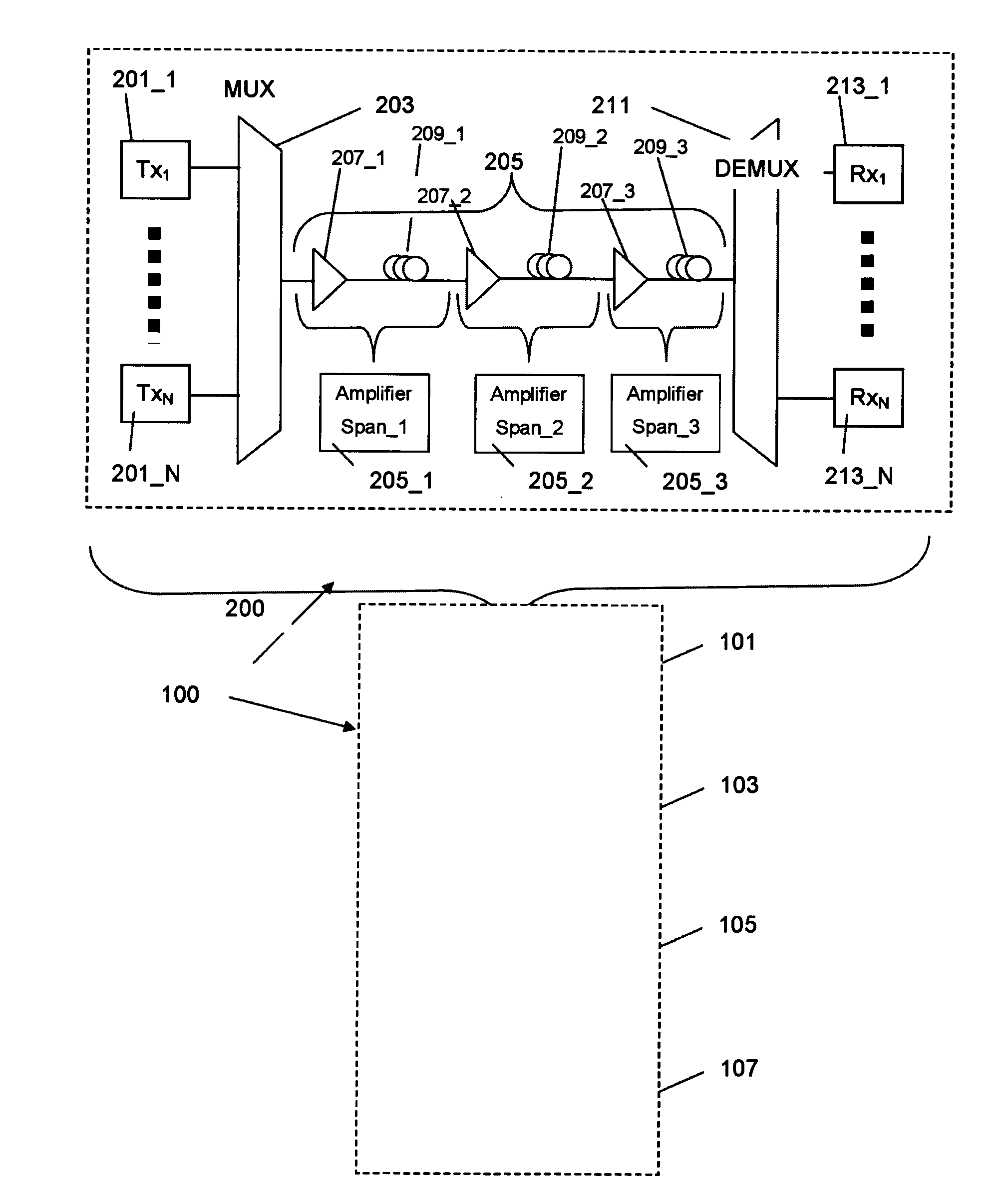
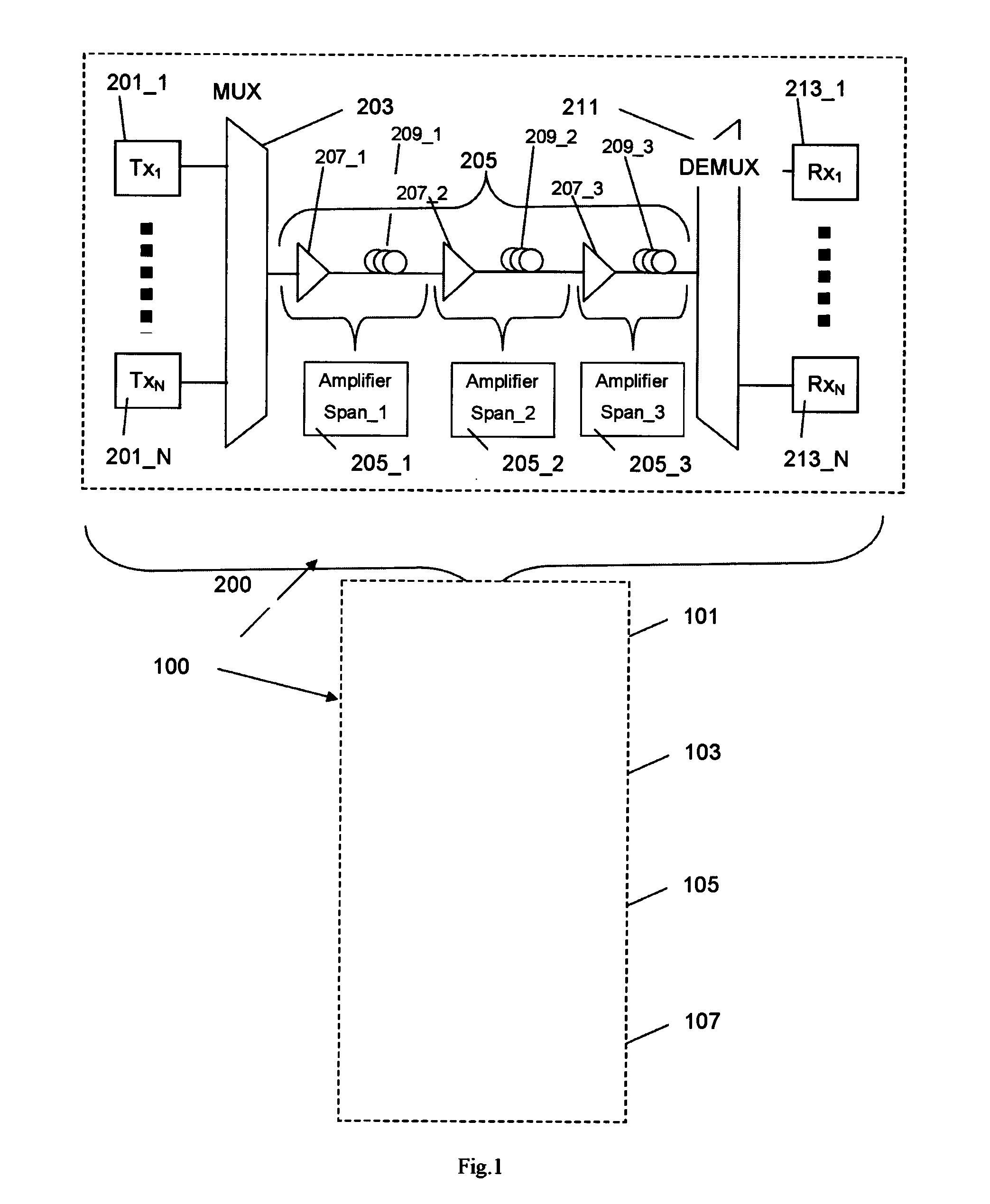
[0089]FIG. 1 shows a block diagram of a method for determining an optical signal-to-noise ratio penalty in an optical network according to an implementation form. The optical signal-to-noise ratio penalty is a measure for a quality of an optical signal transmitted via an optical link between a source optical node and a destination optical node in an optical network 200.

[0090]The optical network 200 comprises a plurality of N optical transmitters 201_1, . . . , 201_N generating N individual optical signals which are multiplexed in a multiplexer 203 into a single multiplexed optical signal. The multiplexed optical signal passes an optical transmission link 205 comprising an exemplary number of three amplifier spans 205_1, 205_2 and 205_3 including optical amplifiers 207_1, 207_2 and 207_3 and optical fibers 209_1, 209_2 and 209_3. At the receiving end a demultiplexer 211 demultiplexes the received multiplexed optical signal into N individual optical receive signals which are switched ...


PUM


Abstract

A method for determining an optical signal-to-noise ratio penalty as a measure for a quality of an optical signal transmitted via an optical link between a source optical node and a destination optical node in an optical network, the method includes collecting information of the optical link; determining a configuration parameter Pconf of the optical link based on the information of the optical link; adjusting the configuration parameter Pconf to an adjusted configuration parameter P′conf according to linear impairments in the optical link; and determining the optical signal-to-noise ratio penalty based on a non-linear function of the adjusted configuration parameter P′conf, the non-linear function accounting for non-linear impairments in the optical link.

Description

CROSS-REFERENCE TO RELATED APPLICATIONS[0001]This application is a continuation of PCT Application No. PCT / CN2011 / 077672, filed on Jul. 27, 2011, entitled “Method and apparatus for determining an optical signal-to-noise ratio (OSNR) penalty”, which is hereby incorporated herein by reference.BACKGROUND OF THE INVENTION[0002]The present invention relates to a method and apparatus for determining an optical signal-to-noise ratio (OSNR) penalty in an optical network. The OSNR penalty serves as a measure for a quality of an optical signal transmitted via an optical link between a source optical node and a destination optical node[0003]In transparent optical networks, the optical signal quality is affected by different impairments like chromatic dispersion (CD), amplifier stimulated emission (ASE) noise, crosstalk, polarization mode dispersion (PMD), self-phase modulation (SPM), cross-phase modulation (XPM), four wave mixing (FWM), etc. When optical networks are designed, the operators ne...

Claims


Application Information

Patent Timeline
Patent Type & Authority Applications(United States)
IPC IPC(8): H04B10/08H04B10/079
CPCH04B10/07953
Inventor YE, YABINWU, TONGZHANG, SEN
Owner HUAWEI TECH CO LTD
Why Eureka
Try Eureka