Inductive touch key switch system including a deflection translation mechanism

a technology of inductive touch and translation mechanism, which is applied in the direction of resistance/reactance/impedence, instruments, pulse techniques, etc., can solve the problems of damage, greater force required, and certain problems when using inductive touch systems, etc., to achieve the effect of reducing the risk of damage, and reducing the service li

Inactive Publication Date: 2014-06-26
DIEHL AKO STIFTUNG
View PDF2 Cites 16 Cited by
  • Summary
  • Abstract
  • Description
  • Claims
  • Application Information

AI Technical Summary

Problems solved by technology

This creates a problem, in that, the thicker the metal used, the greater is the force required to cause enough deflection to be realized as a key press.
To date, expensive technologies utilizing ultrasonic reflections and / or expensive machining / etching of the metal to create local thinner spots in the metal fascia have been used to solve this problem.
Additionally, certain problems can arise when using an inductive touch system, as described in connection with FIG. 1.
For example, if the front panel of the appliance has holes (i.e., for LEDs or the like), there is a chance that liquids (i.e., water, cleaning liquids, etc.) from outside of the appliance will reach the PCB and damage it.

Method used


Image

  • Inductive touch key switch system including a deflection translation mechanism
  • Inductive touch key switch system including a deflection translation mechanism
  • Inductive touch key switch system including a deflection translation mechanism

Examples


Embodiment Construction

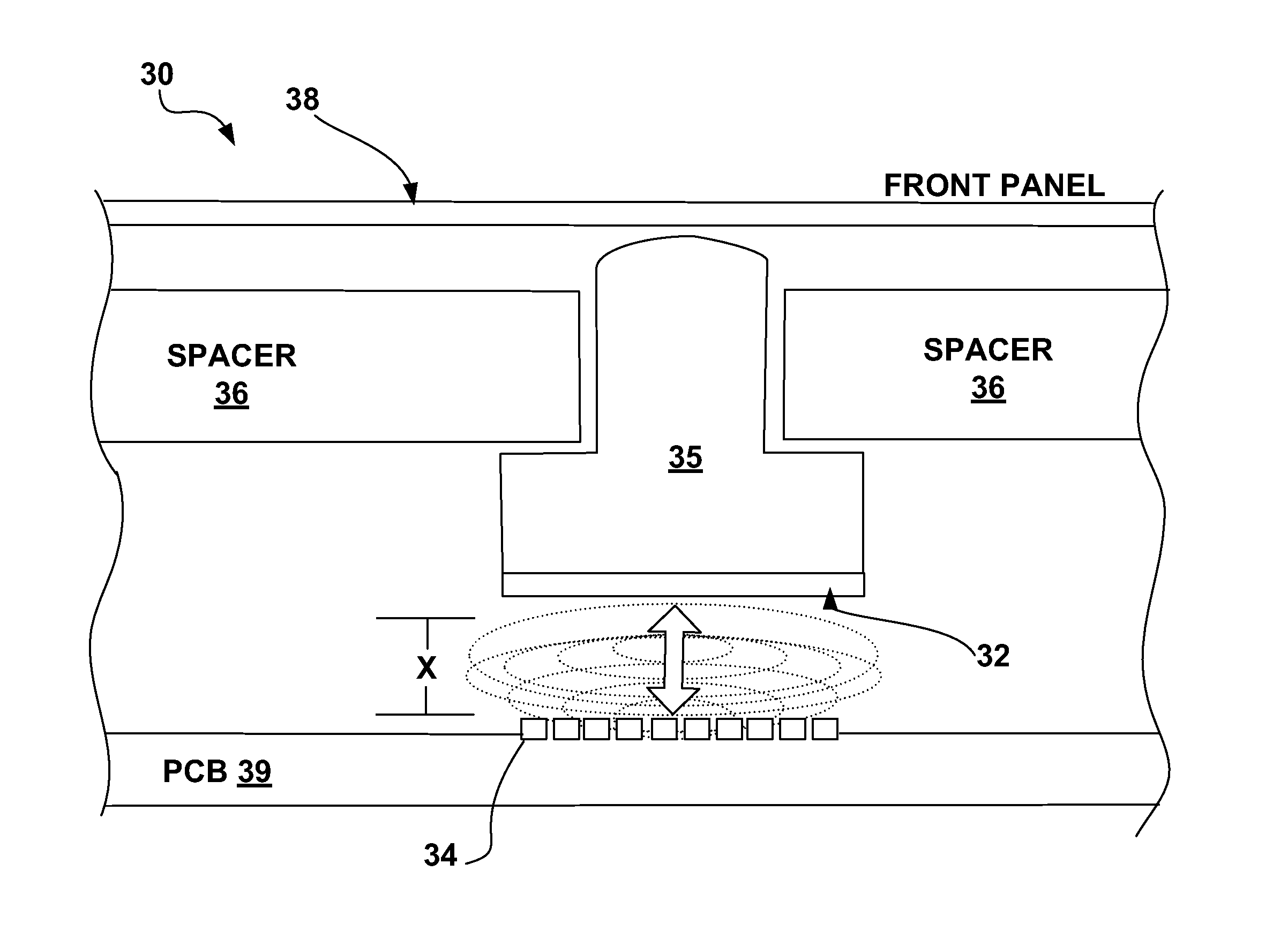
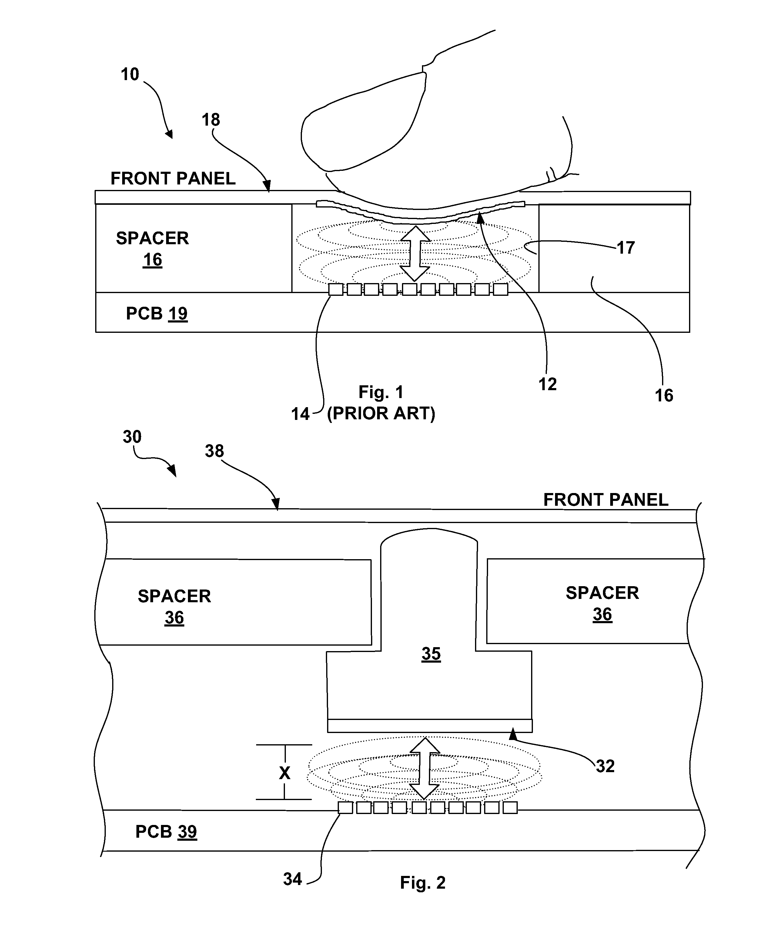
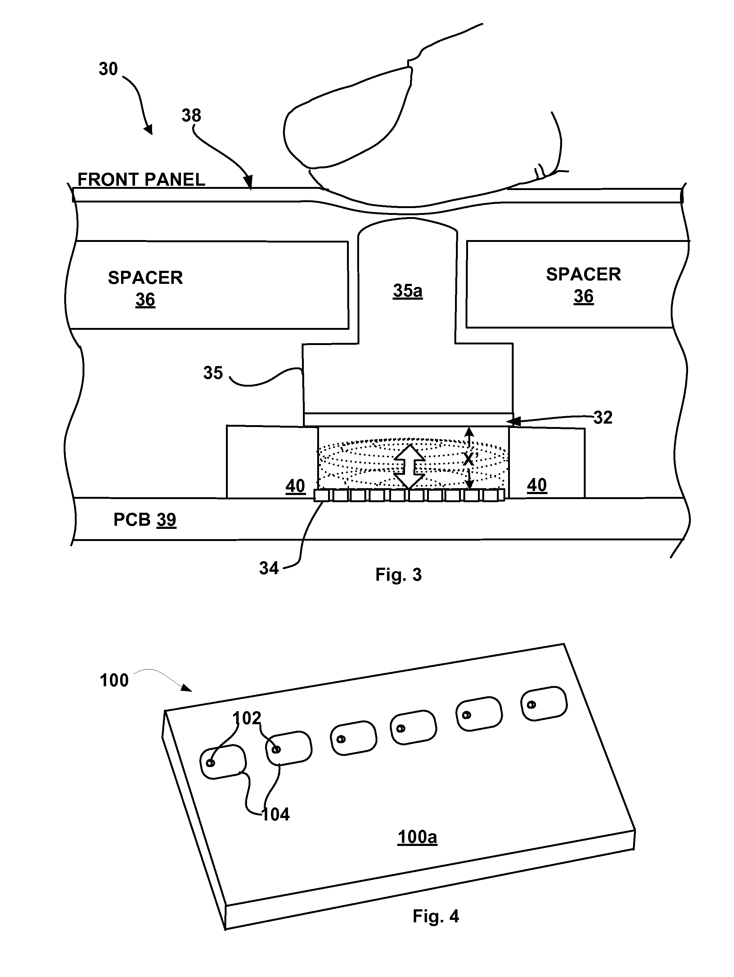
[0028]An inductive touch key switch system, method and circuit are provided herein, which, can be used to amplify and realize a signal by sensing much smaller deflections in the metal being touched than occurs with the MICROCHIP Design. This, in turn, permits the use of thicker metals for the fascia and / or targets in key switch assemblies, which provides the benefits of improving the strength of the materials used and allowing for less force to be applied to the key by the end user.

[0029]It should be noted that the circuit, system and method of the instant invention can be used in connection with other inductive touch key switch systems, for example, with the inductive touch key switch system, assembly and circuit described in U.S. patent application Ser. No. 12 / 696,458 filed on Jan. 29, 2010, and with the inductive touch sensing circuit providing sensitivity compensation described in U.S. patent application Ser. No. 13 / 070,871, filed on Mar. 24, 2011, or even with the systems discl...


PUM

PropertyMeasurementUnit
distanceaaaaaaaaaa
distanceaaaaaaaaaa
thickaaaaaaaaaa

Abstract

A key switch assembly is provided wherein a spacer is used to isolate the key switch sensing circuit from the front panel of the device. A button assembly is provided to translate a deflection of the front panel of the device to a target coupled to a sensor of the sensing circuit.

Description

TECHNICAL FIELD[0001]The instant invention relates to an inductive touch key switch assembly, and more particularly, to an inductive touch key switch system that improves circuit board isolation through the use of a deflection translation mechanism.[0002]Generally, inductive touch key switches and circuits are known. For example, referring now to FIG. 1, MICROCHIP TECHNOLOGY INC. (“MICROCHIP”) of Chandler, Ariz. produces and sells an inductive touch (“touch through metal”) system under the name Inductive mTouch™ and has published an inductive touch key switch assembly design 10 (the “MICROCHIP Design”) that uses a magnetic coupling between a target 12 (made from either solid metal or from a plastic / metal foil combination) and a variable reactance sensor, which in the present case is an inductive sensor or sensor coil 14, separated from one another by a spacer layer 16. Alternately, the metal of the front panel 18 disposed over coil 14 acts as the target 12. The spacer layer 16, whic...

Claims


Application Information

Patent Timeline
Patent Type & Authority Applications(United States)
IPC IPC(8): H03K17/965G01R27/26H01H11/00H03K17/975
CPCH01H2239/024H03K17/97H03K2017/9706H03K17/975H01H11/00H03K17/965G01R27/2611H03K2217/96038Y10T29/49105
Inventor PINTILIUC, SORINDMYTRIW, TONYALVORD, ROBERT
Owner DIEHL AKO STIFTUNG
Why Eureka
Try Eureka