Video Overlays for RC/Autonomous Machine

a technology of autonomous control and video overlay, which is applied in the direction of machine control, process control, television system, etc., can solve the problems of changing the speed of the machine, the operation connection between the operator and the machine is often attenuated, and the remote operator is not physically able to feel the acceleration or deceleration of the machin

Inactive Publication Date: 2014-06-26
CATERPILLAR INC
View PDF5 Cites 9 Cited by
  • Summary
  • Abstract
  • Description
  • Claims
  • Application Information

AI Technical Summary

Problems solved by technology

However, the operational connection between the operator and the machine is often attenuated by the remote connection between the operator and the machine, i.e., by the absence of the operator from the machine cockpit.
For example, a remote operator is not able to physically feel a machine's acceleration or deceleration, or changes in a machine's tilt or inclination.

Method used


Image

  • Video Overlays for RC/Autonomous Machine
  • Video Overlays for RC/Autonomous Machine
  • Video Overlays for RC/Autonomous Machine

Examples


Embodiment Construction

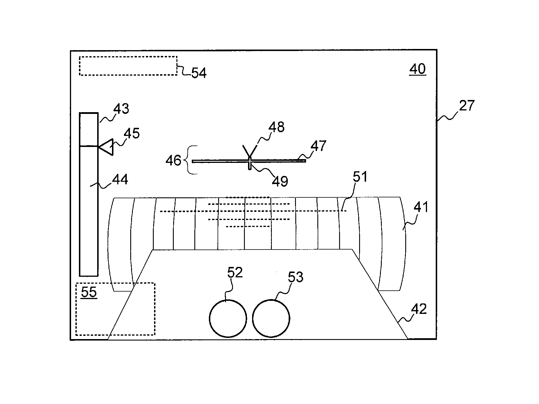
[0016]The present disclosure provides a system and method for remote monitoring of an earthmoving machine using machine video with overlaid graphical indicators. In an embodiment, video data and machine data encompassing machine operational parameters are captured at the machine. The video data and the machine data are transmitted to the operator center, and graphical indicators are then generated at the operator center, with each graphical indicator corresponding to a separate machine operational parameter. The machine video data is then displayed on a display screen at the operator center with the graphical indicators overlaid on the displayed video in multiple separate region of the display screen.

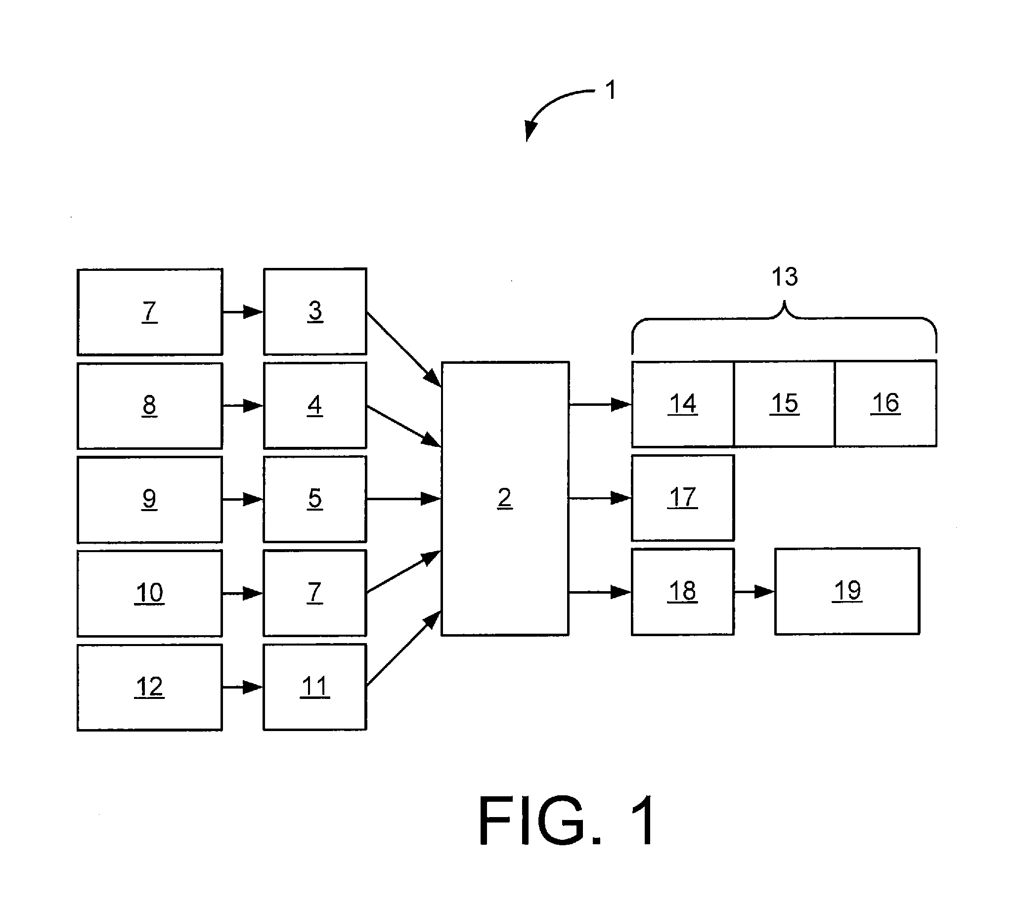
[0017]Having given the above overview, and referring now more specifically to the drawing figures, FIG. 1 is a schematic diagram of a machine data and control system in accordance with an implementation of the disclosed principles. The illustrated machine data and control system 1 inclu...


PUM


Abstract

A method and system for remote monitoring of an earthmoving machine provide machine video with overlaid graphical indicators via a video display at an operator center. In an embodiment, video data and machine data encompassing machine operational parameters are captured at the machine. The video data and the machine data are transmitted to the operator center and graphical indicators are generated at the operator center, with each graphical indicator corresponding to a separate machine operational parameter. The machine video data is then displayed on a display screen at the operator center with the graphical indicators overlaid on the displayed video in multiple separate region of the display screen.

Description

TECHNICAL FIELD OF THE DISCLOSURE[0001]The present disclosure relates to remote and autonomous control of earth-moving machines and, more particularly, relates to a system and method for displaying machine information to a remote operator via the overlay of separate graphical indicators on a video display.BACKGROUND OF THE DISCLOSURE[0002]Many industrial activities require the use of earth moving machines, material lifting and handling machines and other large machines. In order to improve operator safety and productivity while reducing operator fatigue, the operation of such machines is increasingly automated and / or executed via remote control (RC). In this way, an operator may monitor and control a machine from the safety and quiet of an operator center rather than spending the work day in the cockpit of the machine itself.[0003]However, the operational connection between the operator and the machine is often attenuated by the remote connection between the operator and the machine...

Claims


Application Information

Patent Timeline
Patent Type & Authority Applications(United States)
IPC IPC(8): H04N7/18
CPCH04N7/18G05D1/0038G05D2201/0202E02F9/205E02F9/262E02F9/265E02F3/844
Inventor REDENBO, SETHFUNKE, BRIANDUNN, DANIEL
Owner CATERPILLAR INC
Why Eureka
Try Eureka