
Wearable display device

a display device and wearable technology, applied in the field of wearable display devices, can solve the problems of limited mobility, difficult to obtain visual information as well as enjoy culture, and the limitation of people with low vision to live a life like normal peopl

Inactive Publication Date: 2014-06-26
ELECTRONICS & TELECOMM RES INST
View PDF6 Cites 59 Cited by
  • Summary
  • Abstract
  • Description
  • Claims
  • Application Information

AI Technical Summary

Benefits of technology

The wearable display device is designed to help people who are visually impaired, hearing impaired, or disabled overcome barriers in their sight and sound. It includes a communication control module, a signal processing module, and a display module. The device can also capture images through a camera module and display them on the screen. It also has a voice input module for receiving and displaying voice commands. The device can also provide navigation information based on the user's position and map information. Additionally, it can communicate with external devices and receive digital broadcasting signals. The technical effect of this invention is to offer a convenient and practical solution for those who face challenges in accessing information and engaging in activities because of vision or hearing limitations.

Problems solved by technology

It is true that many people benefit from the advancement of IT but it is also true that there are people neglected including the visually impaired or hearing impaired, senior citizens, and the like who do not enjoy the benefits of IT.
Similarly in the case of reading a book, those people have to put a magnifying glass on the book and hold their eye close to the glass to see characters, having a difficulty in obtaining visual information as well as enjoying culture.
Moreover, since those people cannot see the foreground scene clearly, their mobility is considerably restricted.
However, since those devices depend only on images captured through a camera, there is an apparent limitation for those people with low vision to live a life like normal people and as stated above, enjoying the full benefits from the advancement of IT is also not easy for those people.

Method used


Image

  • Wearable display device
  • Wearable display device
  • Wearable display device

Examples


first embodiment

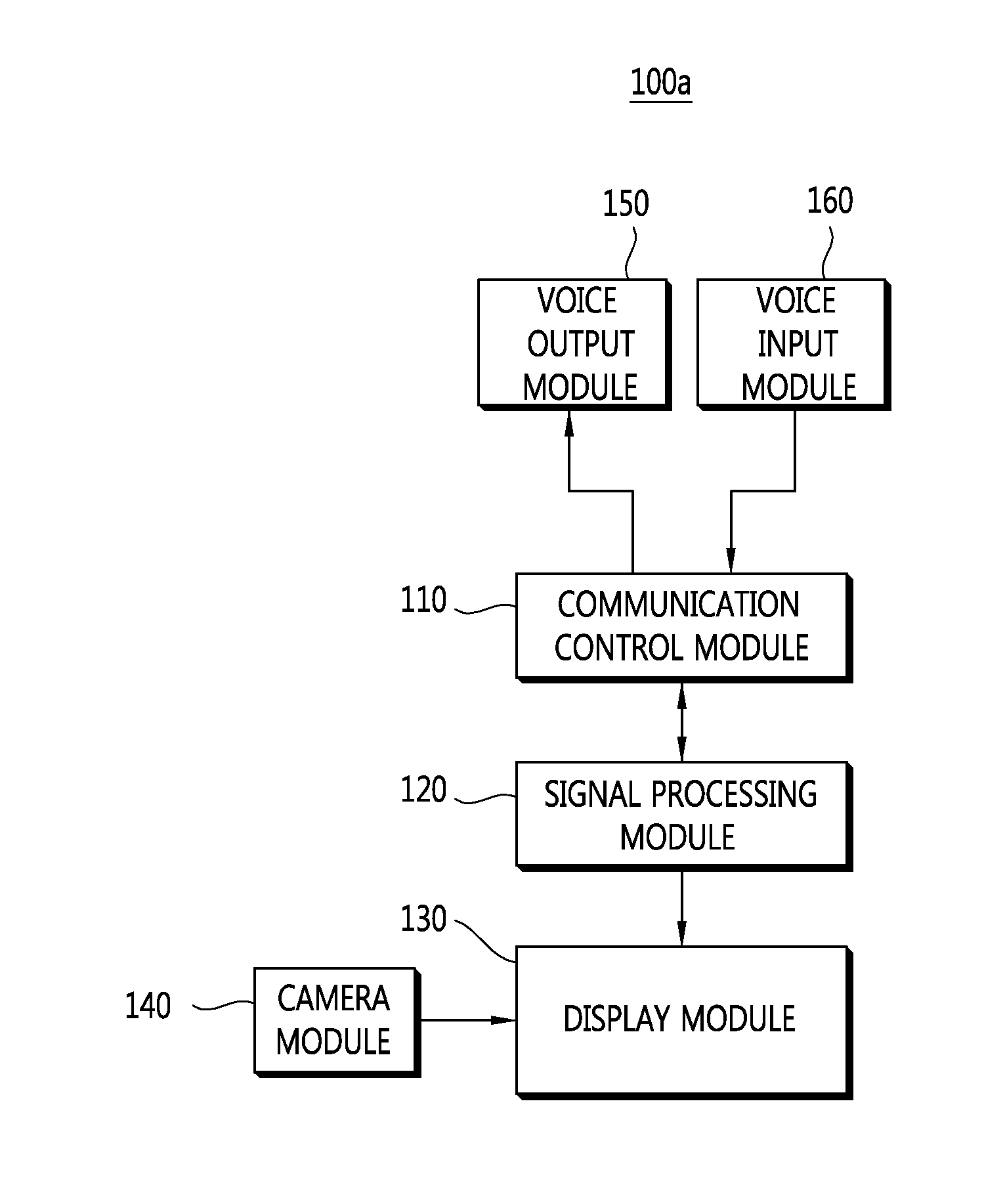
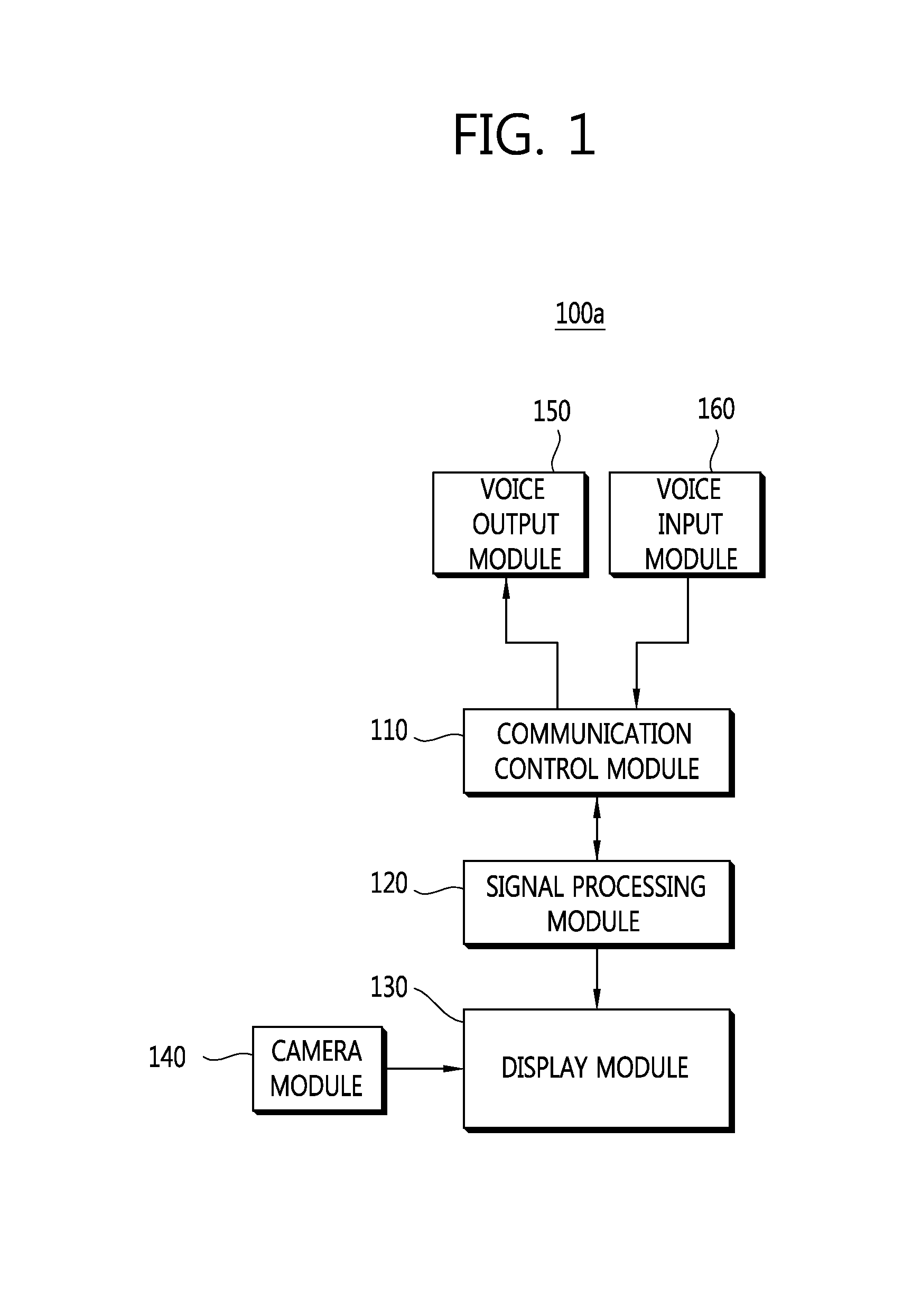
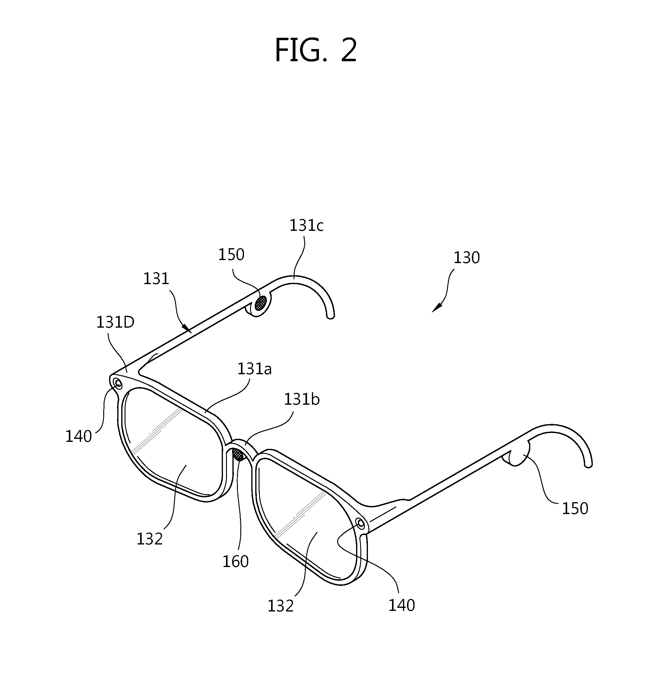
[0032]FIG. 1 illustrates a wearable display device according to a first embodiment of the present invention. FIG. 2 is a perspective view of a display module of a wearable display device according to a first embodiment of the present invention.

[0033]With reference to FIGS. 1 and 2, a wearable display device 100a according to a first embodiment comprises a communication control module 110, a signal processing module 120, and a display module 130.

[0034]The communication control module 110 controls transmission and reception of at least one of a voice signal and an image signal. The signal processing module 120 processes a signal received from the communication control module 110 and extracts the corresponding information from the signal. The display module 130 is prepared in the form of glasses and worn by the user. In other words, the display module 130 comprises a frame 131 and a display unit 132.

[0035]The frame 131 comprises eyewire 131a supporting the display unit 132, bridge 131b...

second embodiment

[0045]FIG. 3 illustrates a wearable display device according to a second embodiment of the present invention.

[0046]With reference to FIG. 3, a wearable display device 100b according to a second embodiment comprises a communication control module 110, a signal processing module 120, a display module 130, and a navigation module 170.

[0047]The navigation module 170 can be installed at the frame 131. The navigation module 170 comprises a position information receiving unit 171, a map controller 172, and a direction indicating unit 173. A GPS receiver may be used for the position information receiving unit 171. The position information receiving unit 171 receives position information of the user wearing a display module 130. The map controller 172 is connected to the communication control module 110. The map controller 172 controls a map according to a map control signal input of the user. The direction indicating unit 173 displays on the display module 130 a direction along which the us...

third embodiment

[0050]FIG. 4 illustrates a wearable display device according to a third embodiment of the present invention.

[0051]With reference to FIG. 4, a wearable display device 100c according to a third embodiment comprises a communication control module 110, a signal processing module 120, a display module 130, and a first communication module 181.

[0052]A wireless communication module employing short range wireless communication technology such as Wi-Fi, Bluetooth, and so on can be used for the first communication module 181. The first communication module 181 can be connected to an external device 170 which can be carried by the user and is capable of short range communication such as a smart device, portable camera, pen-type camcorder, and so on.

[0053]Therefore, a wearable display device 100c according to the third embodiment receives data stored in a smart device, images captured by a portable camera, images scanned by a pen-type camcorder, and the like and displays the corresponding infor...


PUM


Abstract

The present invention provides a wearable display device which enables the visually impaired, hearing impaired, and disabled to live a normal living and furthermore, enables them to enjoy various benefits due to the advancement of IT.A wearable display device according to the present invention comprises a communication control module controlling transmission and reception of a signal; a signal processing module processing the signal input to the communication control module and extracting information from the signal; and a display module being worn by a user in the form of glasses and displaying the information.

Description

CROSS-REFERENCE TO RELATED APPLICATIONS[0001]This application claims the benefit of priority of Korean Patent Application No. 10-2012-0131346 filed on Dec. 20, 2012, which is incorporated by reference in their entirety herein.BACKGROUND OF THE INVENTION[0002]1. Field of the Invention[0003]The present invention relates to a wearable display device and more particularly, a wearable display device worn by a user in the form of glasses and displaying predetermined information for the user.[0004]2. Discussion of the Related Art[0005]Information technology (IT) including location based services making use of global positioning system (GPS) and indoor location technology; display technology; wireless communication technology; and so on provides the users with a host of benefits such as convenience of living.[0006]Particularly, advancement of display technology has reached a point of commercialization of thin film type of flexible display and about 4 inch size of OLED flexible display has b...

Claims


Application Information

Patent Timeline
Patent Type & Authority Applications(United States)
IPC IPC(8): G02B27/01G10L15/22H04N5/232
CPCG02B27/017H04N5/23293G10L15/22G10L15/26G02B2027/0138G02B2027/014G02B27/02
Inventor AHN, CHUNG HYUN
Owner ELECTRONICS & TELECOMM RES INST
Learn More